APOD: 2026 October 13 – Desert Stairway to Heaven

APOD

Astronomy Picture of the Day

Discover the cosmos! Each day a different image or photograph of our fascinating universe is featured, along with a brief explanation written by a professional astronomer.

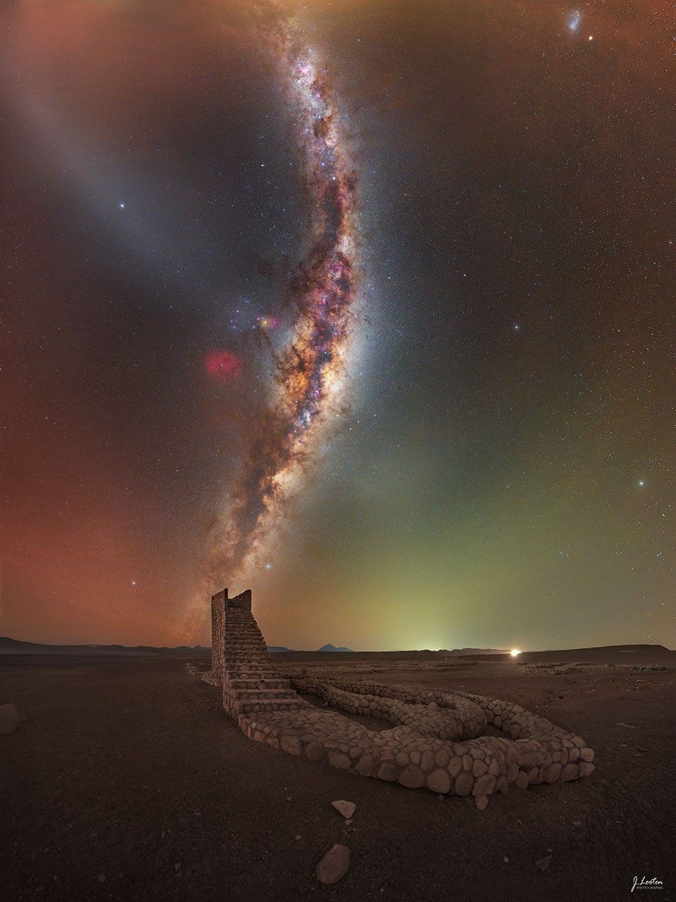
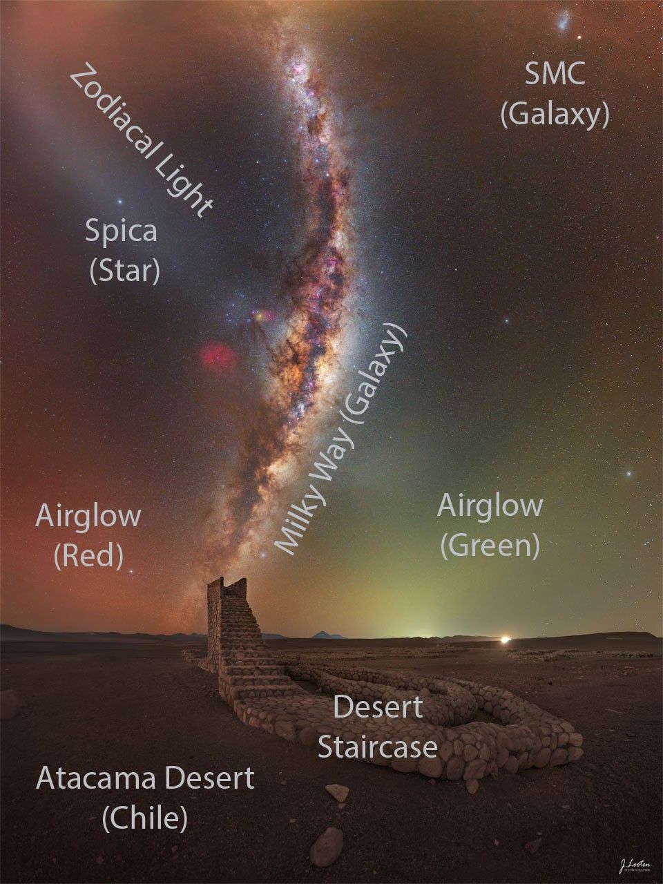
The Milky Way galaxy rises from the horizon and curves upward in the sky. In the foreground, a rock pathway is seen that culminates in a staircase that ends abruptly. The Milky Way band appears to be a continuation of the staircase. Please see the explanation for more detailed information.The Milky Way galaxy rises from the horizon and curves upward in the sky. In the foreground, a rock pathway is seen that culminates in a staircase that ends abruptly. The Milky Way band appears to be a continuation of the staircase. Please see the explanation for more detailed information.

Desert Stairway to Heaven

Explanation: This stairway in Chile brings you only a little bit closer to heaven. But ooh, the sky above it makes you wonder. For example, you may wonder about the dark lane of our own Milky Way galaxy rising behind the expansive Atacama Desert in Chile, the band of zodiacal light on the upper left, the green and red airglow just above the horizon, the star Spica in the zodiacal light stripe, and, at the very top on the right, the Small Magellanic Cloud galaxy. The Desert Staircase sculpture is in the foreground, and this image was timed to catch the picturesque peering perch just in front of the near-vertical Milky Way band. Upon close inspection of the horizon you can find, left to right, some Andes Mountains, the Licancabur volcano, and the town lights of San Pedro de Atacama. The featured wide-angle composite was captured in July 2025.

Tomorrow’s picture: space bees

Date October 13, 2026
Credit & Copyright Julien Looten
Authors & editors: Robert Nemiroff, Jerry Bonnell, Cecilia Chirenti, Keighley Rockcliffe
A service of: ASD at NASA / GSFC,
NASA Science Activation & Michigan Tech. U.

Source: science.nasa.gov

NASA Science, Cargo Launch on 35th SpaceX Resupply Mission to Station

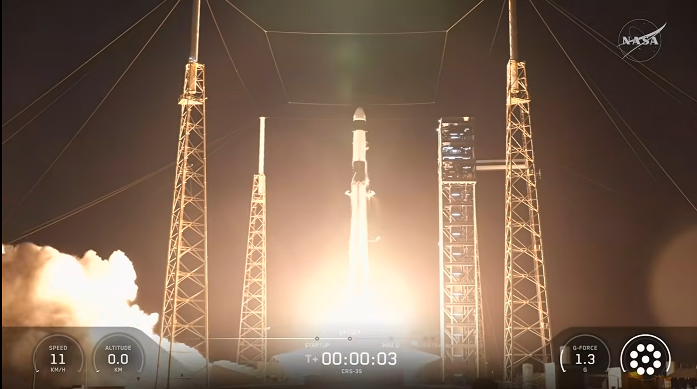
A SpaceX Falcon 9 rocket and Dragon spacecraft launched on Tuesday, Oct. 13, 2026, from Space Launch Complex 40 at Cape Canaveral Space Force Station in Florida as part of the company’s 35th Commercial Resupply Services mission to the International Space Station for NASA.
Credit: NASA

NASA’s SpaceX 35th commercial resupply mission lifted off at 6:33 a.m. EDT Tuesday aboard a Falcon 9 rocket from Space Launch Complex 40 at Cape Canaveral Space Force Station in Florida, carrying more than 6,300 pounds of supplies and hardware, bound for the International Space Station. Following its successful launch, the SpaceX Dragon spacecraft will carry new scientific experiments, cargo, and the final pair of International Space Station Roll-Out Solar Arrays to the orbiting laboratory.

Dragon is scheduled to autonomously dock at 11 a.m., Thursday, Oct. 15, to the space-facing port of the space station’s Harmony module. NASA will stream rendezvous and docking coverage beginning at 9:15 a.m., through a variety of platforms. Learn where to watch online:

https://www.nasa.gov/live

The final pair of solar arrays will complete the space station’s power system augmentation, boosting available electricity for research, operations, and the station’s safe, controlled deorbit. Astronauts will install the arrays during a series of spacewalks planned for later this fall.

Dragon also is delivering several new experiments, including hardware to manufacture artificial retinas in microgravity that could help restore vision for patients on Earth and 3D heart tissue models to advance large-scale drug testing on future space missions. Dragon also will carry materials to study how a new type of glass is formed in microgravity, and brain organoids that could uncover potential treatment targets for neurodegenerative diseases like Alzheimer’s, Parkinson’s, and multiple sclerosis.

These are just a sample of the hundreds of investigations conducted aboard the orbiting laboratory in the areas of biology and biotechnology, physical sciences, and Earth and space science. Research and technology investigations taking place aboard the space station benefit people on Earth and lay the groundwork for other agency deep space missions. As part of NASA’s Artemis program, the agency will send astronauts to the Moon to prepare for future human exploration of Mars, inspiring the world through discovery in a new Golden Age of innovation and exploration.

The Dragon spacecraft is scheduled to remain at the space station until mid-November when it will depart and return to Earth with time-critical research and cargo, splashing down off the coast of California.

Learn more about the International Space Station, its research, and crew, at:

https://www.nasa.gov/station

-end-

Joshua Finch / Jimi Russell
Headquarters, Washington
202-358-1100
[email protected] / [email protected]

Steven Siceloff
Kennedy Space Center, Fla.
321-876-2468
[email protected]

Sandra Jones / Joseph Zakrzewski
Johnson Space Center, Houston
281-483-5111
[email protected] / [email protected]

Source: www.nasa.gov
NASA JPL Testing Readies Voyager Technologies Lander for Moon Mission

4 min read

Preparations for Next Moonwalk Simulations Underway (and Underwater)

A commercial lander that will be at the forefront of NASA’s efforts to establish a Moon Base, humanity’s first lunar outpost, has passed a series of critical tests at the agency’s Jet Propulsion Laboratory in Southern California. The tests simulated the extreme temperatures and vacuum of space, as well as the intense shaking and ear-splitting roar of launch. Results show that Voyager Technologies’ Griffin Mission One (Griffin-1) spacecraft is ready to survive the rigors of space exploration.

As part of NASA’s CLPS (Commercial Lunar Payload Services) initiative within the Moon Base Program, Griffin-1 is expected to launch later this year aboard a SpaceX Falcon Heavy rocket. It will deliver more than 1,100 pounds (455 kilograms) of cargo to Nobile Crater near the lunar South Pole, which categorizes it as an infrastructure-class lander. Griffin-1 will carry 10 science and technology demonstrations from six countries, including the largest commercial payload ever delivered to the Moon, Astrolab’s FLIP (FLEX Lunar Innovation Platform) rover.

“NASA JPL’s Environmental Test Laboratory has been putting robotic explorers to the test since the Ranger program gave us NASA’s first up-close views of the Moon’s surface in the mid-1960s. We’re proud to provide our expertise and facilities to support this new phase of commercial lunar exploration,” said Charles Whetsel, manager, Exploration Systems Development Office at JPL.

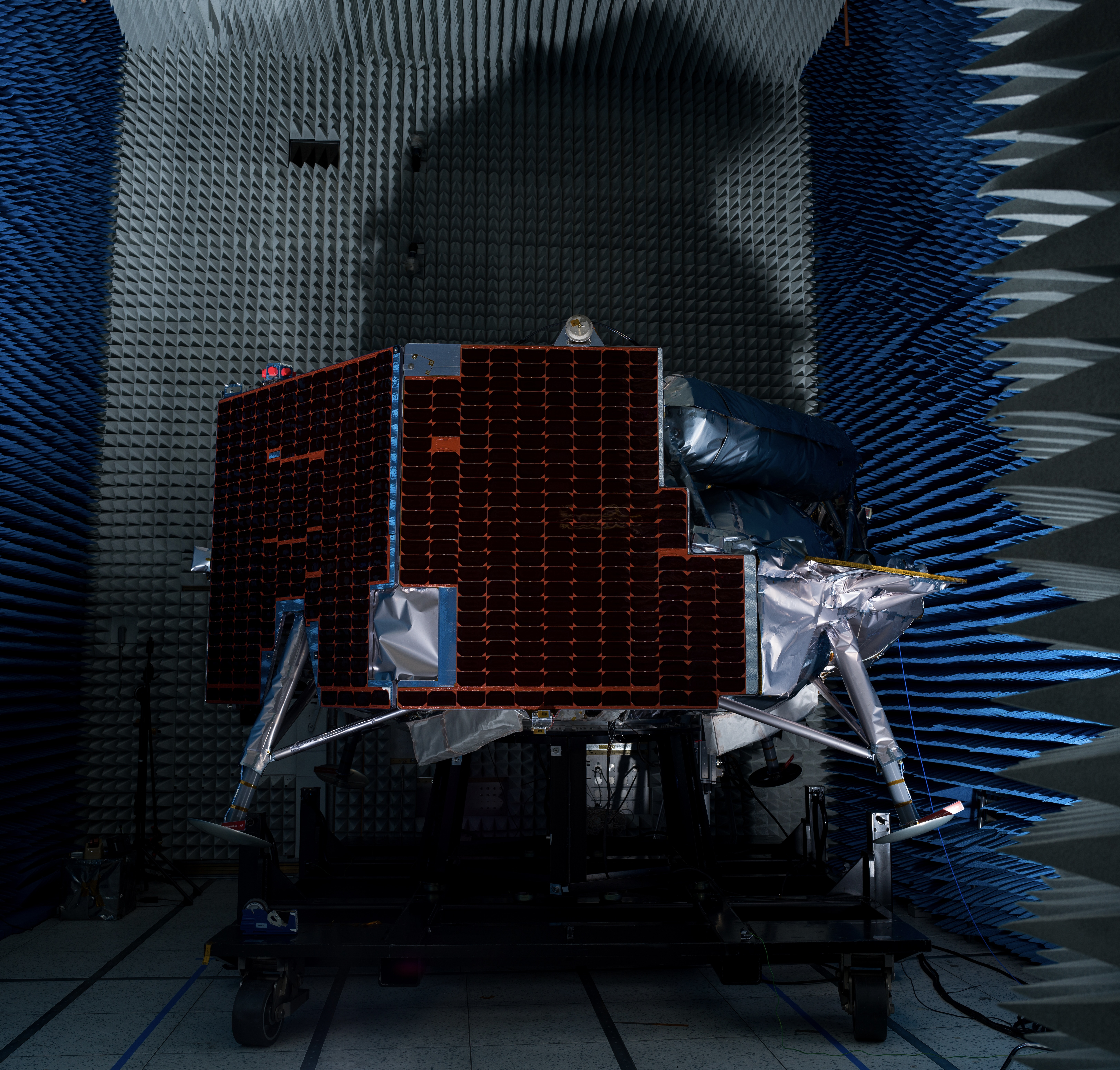
A lunar lander equipped with dark solar panels and foil-wrapped legs sits on a platform inside a dark anechoic chamber lined with blue and gray foam spikes.
Long foam spikes that absorb sound waves and electromagnetic waves cover the walls of a specialized anechoic chamber at JPL where Voyager Technologies’ Griffin-1 underwent electromagnetic interference and electromagnetic compatibility testing.
NASA/JPL-Caltech

Griffin-1’s testing journey

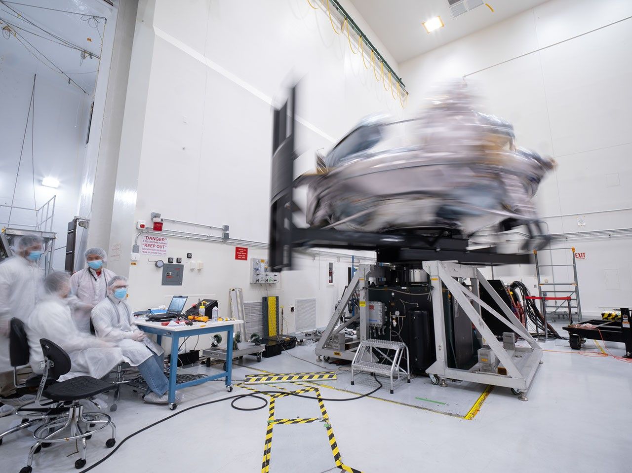
Testing began in July after the 2,789-pound (1,265-kilogram) spacecraft took a cross-country road trip from Voyager Lunar Systems’ manufacturing facilities in Pittsburgh to JPL in the San Gabriel Mountain foothills. Engineers spun the spacecraft on a special table to measure its mass properties, a test that enables them to look for any unexpected wobbles as they assess how the lander will move through space. Data gathered in mass properties testing is key to understanding the spacecraft’s readiness for navigation in flight and landing on the lunar surface.

To make sure signals from the spacecraft’s electronic components don’t interfere with one another, Griffin-1 underwent electromagnetic interference and electromagnetic compatibility testing inside what’s called an anechoic chamber, in which long foam spikes line the walls to absorb sound and electromagnetic waves.

During vibration testing, hundreds of sensors monitored Griffin-1 as a “shaker table” rattled it in three directions, with increasingly intense force, to simulate the ride out of Earth’s atmosphere on a massive rocket. To mimic the roar of launch, giant horns, powered by compressed nitrogen gas, blasted the spacecraft with up to 153 decibels inside a sealed acoustic chamber.

Environmental testing took place in several clean-room facilities at JPL, culminating in the 25-Foot Space Simulator, a thermal vacuum chamber listed on the National Register of Historic Places for its role in supporting historic missions like those of the Ranger, Surveyor, Mariner, and Voyager programs. Dozens of other missions (along with plenty of upgrades to the testing facility) have followed over the decades, including the Perseverance Mars rover and Europa Clipper.

Beneath the thermal vacuum chamber’s soaring 85-foot (26-meter) ceiling, for about two weeks, Griffin-1 alternately baked at up to 167 degrees Fahrenheit (75 degrees Celsius) and froze at temperatures as low as minus 148 F (minus 100 C). This testing simulates the temperature extremes the lander will experience during its journey through the vacuum of space and its operations on the lunar surface.

“Griffin-1 is being built for a historic purpose: to deliver the infrastructure and capabilities to the Moon. Seeing the spacecraft complete this demanding environmental testing is a major milestone because it demonstrates that Griffin-1 is ready for the extreme journey ahead: launch, through deep space, to the lunar South Pole,” said John Thornton, executive vice president, Voyager. “This spacecraft represents a new era of commercial lunar exploration, where missions like Griffin-1 are laying the groundwork for the Moon Base and helping turn sustained lunar exploration from a vision into a reality.”

After proving its mettle at JPL, Griffin-1 has returned to Voyager Lunar Systems’ facility for final assembly. Next up: launch-readiness operations before shipment to Cape Canaveral.

To learn more about the Moon Base, visit:

https://www.nasa.gov/moonbase

Media Contact
Melissa Pamer
Jet Propulsion Laboratory, Pasadena, Calif.
626-314-4928
[email protected]

2026-071

Source: www.nasa.gov

TB 26-08 Complex Modes in Lightly Damped Structural Systems: A Two-Mode Interaction Perspective

For more information, contact Joel W. Sills, Langley Research Center, [email protected]

Download the PDF version

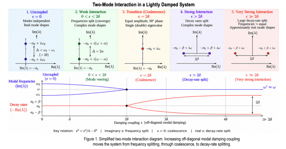
Complex mode shapes can emerge in a linear structure even when overall damping is low. This behavior can occur when two structural modes are closely spaced in frequency and are coupled through nonproportional damping. As the damping interaction increases, the two modal frequencies move toward one another while the mode shapes become increasingly complex. At a critical interaction level, the two frequencies coalesce. Beyond this point, the frequencies remain approximately equal while the modal decay rates separate. At very strong interaction, the mode shapes become approximately real again, but as different combinations of the original uncoupled modes. This framework provides a simple physical interpretation of mode veering, complex mode formation, eigenvalue coalescence, and decay-rate splitting in lightly damped structural systems.

Why Complex Modes Can Appear at Low Damping
Classical modal analysis often treats lightly damped structures as nearly proportional systems with real mode shapes. That interpretation can become misleading when two modes are closely spaced. In modal coordinates, nonproportional damping introduces an off-diagonal coupling term ε. The relevant question is therefore not simply whether damping is small, but whether the coupling is large relative to the baseline half-frequency separation δ=(ω2 -ω1 )/2.

Reduced Perturbation Framework
For a closely spaced pair, define the central eigenvalue λ0 ≈-ζω +iω and write the coupled eigenvalues as λ1,2=λ0 ±s. Under lightdamping and close-mode asymptotic assumptions, the local quartic eigenvalue problem reduces to s²=ε²/4-δ². This single relation determines the direction of eigenvalue separation in the complex plane, as summarized in Figure. 1. For 0<ε 2δ, s = ±β and the split is predominantly horizontal (decay rate). As ε increases further, β increases and the two decay rates separate more strongly while their frequencies remain approximately equal.

Engineering Interpretation and Recommended Practice
Complexity in an identified mode shape should not automatically be interpreted as evidence of heavy damping, nonlinearity, or poor test data. For a close modal pair, examine the complex poles together with mode-shape phase. Frequency convergence accompanied by near-quadrature modal components is consistent with the imaginary-s regime; nearly equal frequencies accompanied by decay-rate separation is consistent with the real-s regime. The framework also provides a practical testanalysis bridge: s=(λ1 -λ2 )/2 can be obtained from identified poles, while δ can be estimated from the uncoupled or pretest analytical modal spacing. These quantities can then be used to estimate the effective interaction strength and determine proximity to the transition boundary.

References

1. Majed, A., Henkel, E. E., and Sills, J. W., Emergence of Complex Modes in Lightly Damped Structural Systems: A Reduced Perturbation Framework, NASA/TM-20260007553, August 2026.

Source: www.nasa.gov
Voyager Technologies’ Griffin-1 Completes Environmental Testing at NASA JPL

3 Min Read

Voyager Technologies’ Griffin-1 Completes Environmental Testing at NASA JPL

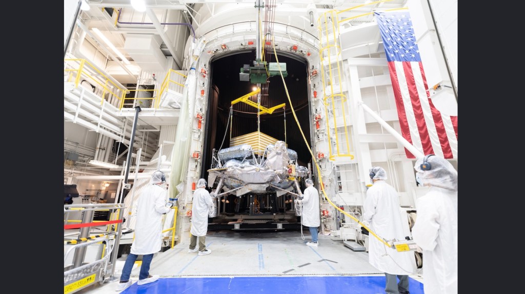
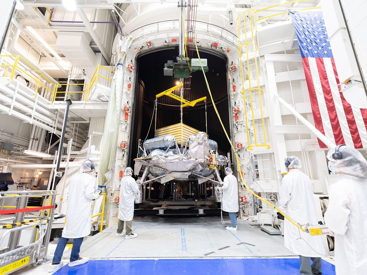
Engineers in white clean-room garb and hairnets guide a spacecraft suspended from a crane into a large thermal vacuum chamber inside a high-bay facility with an American flag hanging on the wall.

PIA26708

Credits:
NASA/JPL-Caltech

Description

A lunar lander from Voyager Technologies completed nearly three months of environmental testing at NASA’s Jet Propulsion Laboratory in Southern California in late September 2026. The tests demonstrate that the spacecraft is prepared to face the harsh conditions of launch, its journey to the Moon, and landing on the surface. Its final trial was in JPL’s historic 25-Foot Space Simulator, a thermal vacuum chamber listed on the National Register of Historic Places for its role in supporting historic missions like those of the Ranger, Surveyor, Mariner, and Voyager programs. 

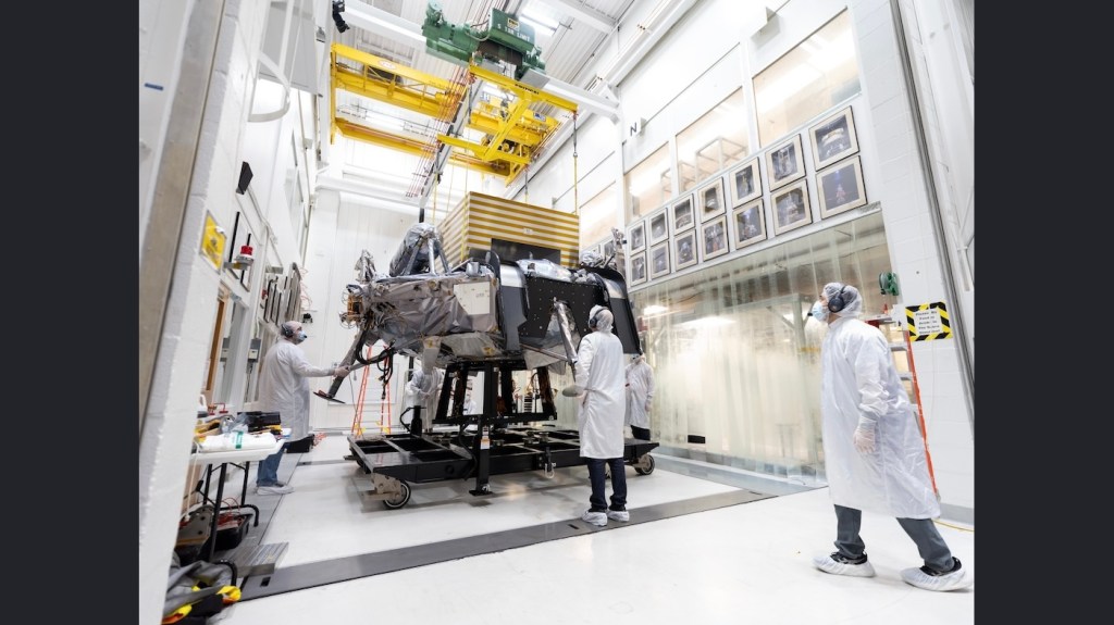
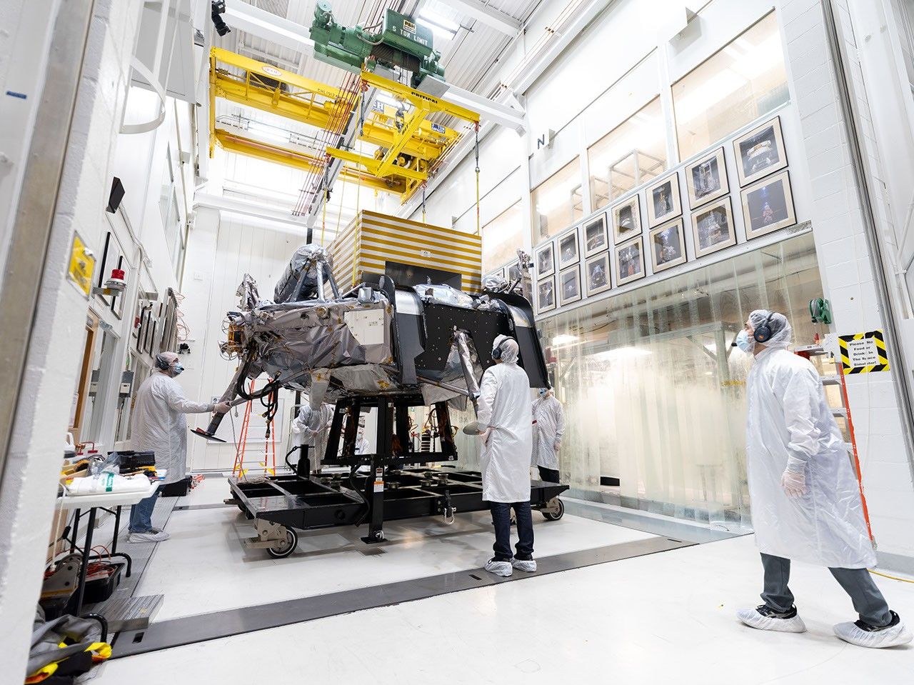
Engineers and technicians on Aug. 31, 2026, used a crane to position the spacecraft within the towering chamber, where Griffin-1 alternately baked at up to 167 degrees Fahrenheit (75 degrees Celsius) and froze at temperatures as low as minus 148 F (minus 100 C). This thermal vacuum testing simulates the extreme temperatures the spacecraft will experience during its mission. The yellow-striped box atop the lander simulates a payload that will later be attached to the spacecraft: Astrolab’s FLIP (FLEX Lunar Innovation Platform) rover.

Engineers in white clean-room garb monitor a large spacecraft as it is hoisted by a yellow overhead crane in a hallway in a bright, high-tech laboratory. Framed photos line both sides of the hallway.
Figure A

In Figure A, engineers and technicians move Griffin-1 through a hallway leading to the 25-Foot Space Simulator on Aug. 31. The corridor is lined with photographs of some of the historic spacecraft that have been tested in the facility since the 1960s.

A lunar lander equipped with dark solar panels and foil-wrapped legs sits on a platform inside a dark anechoic chamber lined with blue and gray foam spikes.
Figure B

Figure B shows Griffin-1 on July 29 in an anechoic chamber for electromagnetic interference and electromagnetic compatibility testing, which ensures signals from the spacecraft’s electronic components don’t interfere with one another. Long foam spikes line the chamber walls to absorb sound waves and electromagnetic waves.

Engineers in white clean-room frocks monitor a silvery spacecraft spinning so rapidly it’s blurred on a test rig inside a bright laboratory.
Figure C

In Figure C, taken on July 20, Griffin-1 rotates rapidly on a special table to measure its mass properties, enabling engineers to look for any unexpected wobbles as they assess how the vehicle will move through space — vital information for determining the spacecraft’s readiness for flight and surface operations.

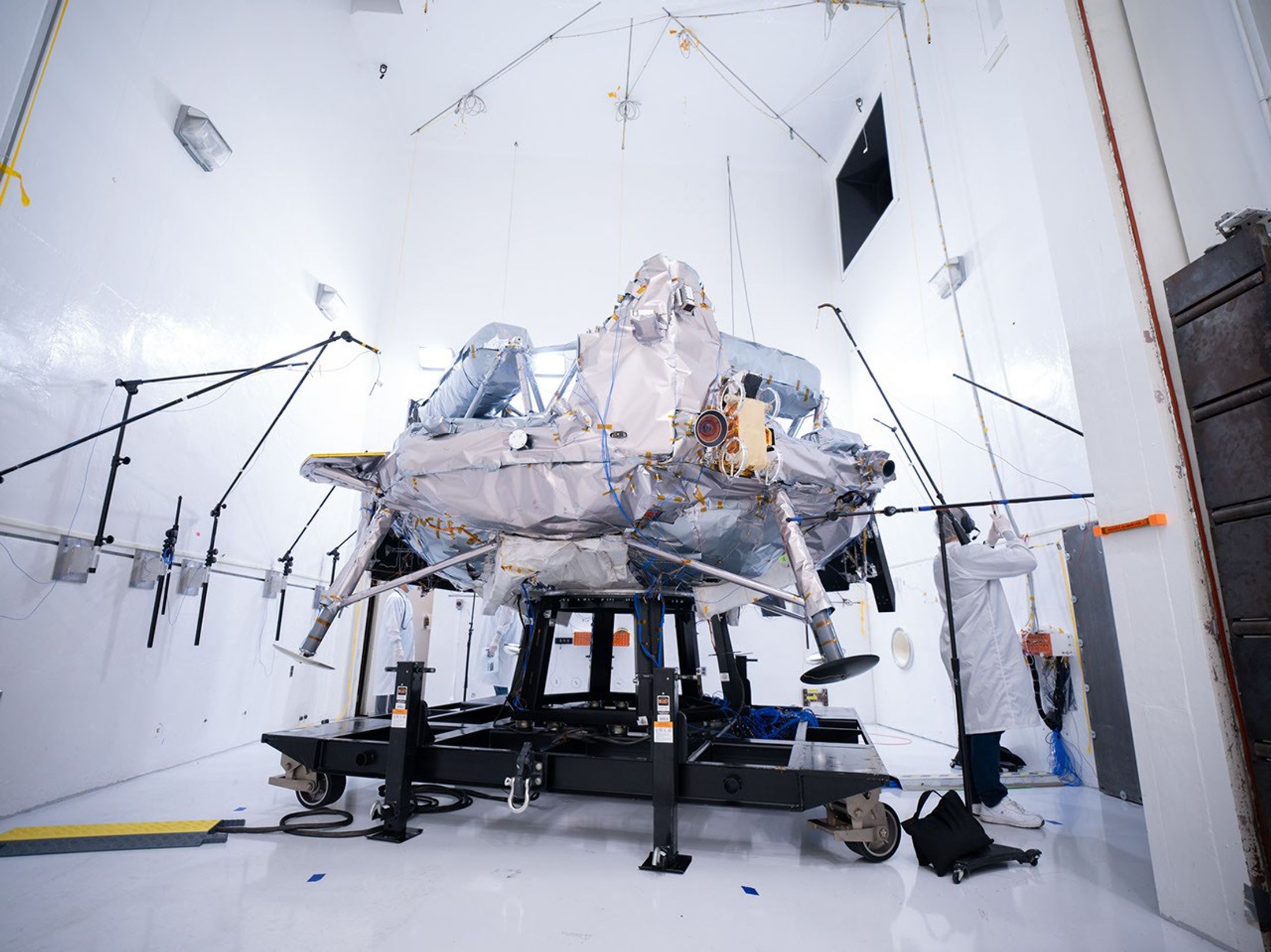
A silvery spacecraft sits on a test frame surrounded by microphones and testing equipment inside a bright white acoustic test chamber, while an engineer in a lab coat works nearby.
Figure D

In Figure D, microphones are arrayed around Griffin-1 on Aug. 12 during acoustic testing in which giant horns powered by compressed gaseous nitrogen blast the spacecraft with up to 153 decibels inside the sealed acoustic chamber to mimic the roar of launch. 

Griffin-1 also endured vibration testing, during which hundreds of sensors monitored the spacecraft as a “shaker table” rattled it in three directions — with increasingly intense force — to simulate the ride out of Earth’s atmosphere atop a rocket.

After proving its mettle at JPL, Griffin-1 was shipped back across the country to Voyager Lunar Systems’ Pittsburgh facility for final assembly. Part of NASA’s CLPS (Commercial Lunar Payload Services) initiative within the Moon Base Program, Griffin-1 is expected to launch in late 2026 aboard a SpaceX Falcon Heavy rocket. The infrastructure-class lander will deliver more than 1,100 pounds (455 kilograms) of cargo — 10 payloads from six countries — to Nobile Crater near the lunar South Pole.

Caltech in Pasadena, California, manages JPL for NASA.

Source: science.nasa.gov

Transporter-18 SmallSats Encapsulation

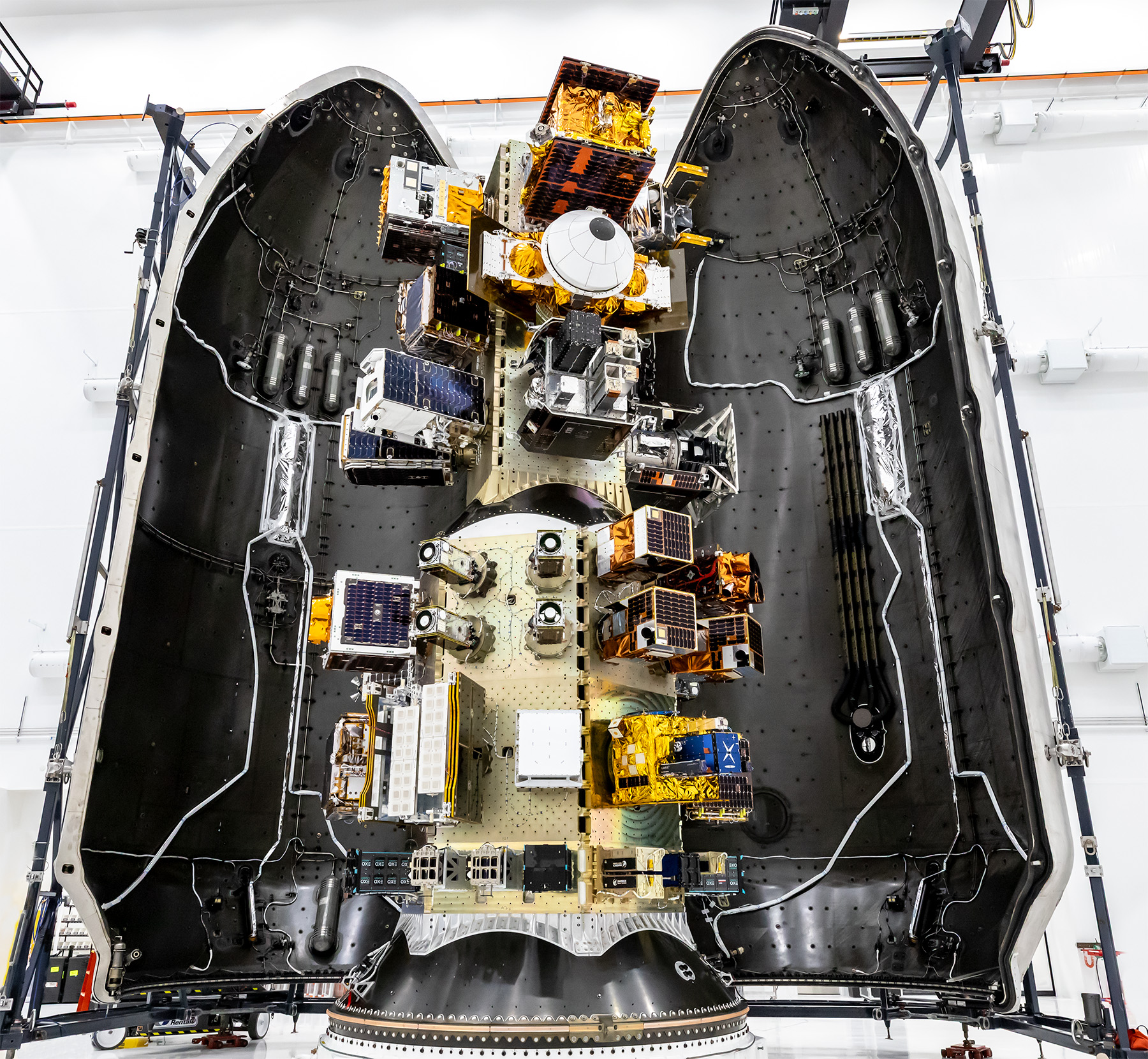
View of a SpaceX payload fairing interior showing mounted satellites and hardware arranged along the center structure, surrounded by the curved black fairing walls.
SpaceX

Three NASA-supported small spacecraft, along with many commercial payloads, are shown before being encapsulated in a SpaceX Falcon 9 ahead of launch on Oct. 1, 2026. The ASCENT Propulsion Dual Mode CubeSat, the Supernova Remnants and Proxies for ReIonization Testbed Experiment (SPRITE) CubeSat, and the Small Spacecraft Propulsion and Inspection Capability (SSPICY) mission will demonstrate new propulsion technologies, study how galactic dust and high-energy radiation move through galaxies, and advance capabilities for inspecting inactive satellites.

Image credit: SpaceX

Source: www.nasa.gov
Perseverance Navcam Image Marks Record Drive

1 Min Read

Perseverance Navcam Image Marks Record Drive

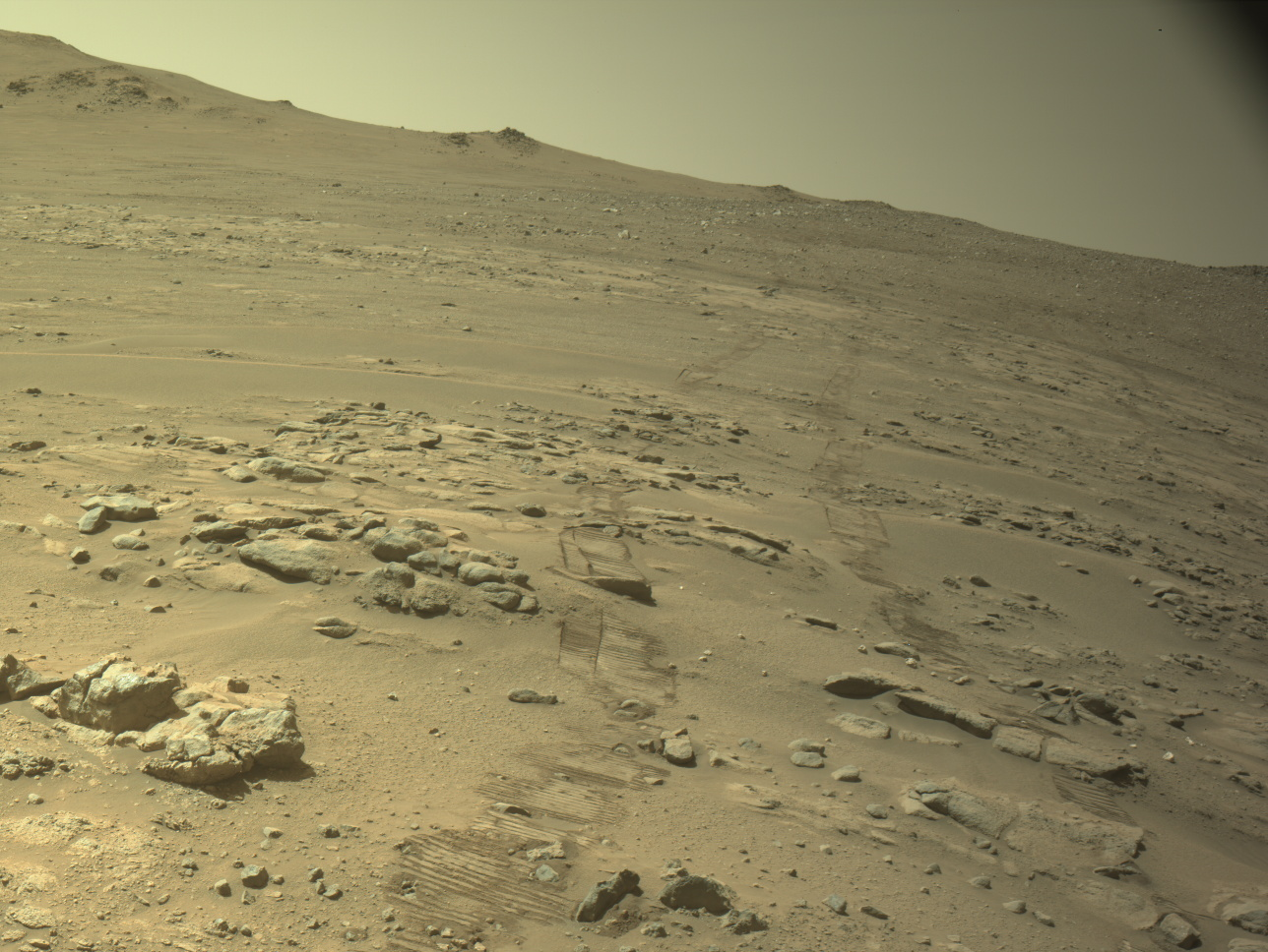
Rover tracks press into the sand of a rocky, sloping Martian landscape, leading upward toward a distant ridge under a pale, hazy sky.

PIA26812

Credits:
NASA/JPL-Caltech

Description

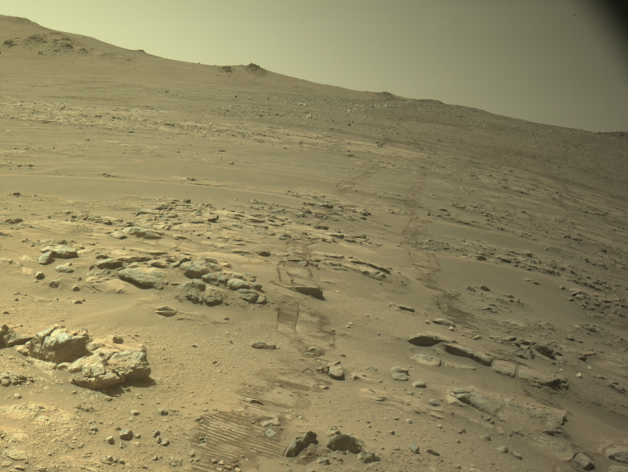
Rover tracks and a rocky Martian landscape are shown in this image captured by one of the navigation cameras (navcams) aboard NASA’s Perseverance Mars rover on Oct. 11, 2026, the 2,006th Martian day, or sol, of the mission. During that sol’s drive, spanning 299.6 feet (91.31 meters), the mission passed a major milestone: pushing Perseverance’s total driving distance beyond that of the agency’s Opportunity rover, which logged 28.06 miles (45.16 kilometers) during its 15-year mission on Mars.

NASA’s Jet Propulsion Laboratory, which is managed for the agency by Caltech in Pasadena, California, built and manages operations of the Perseverance rover on behalf of the agency’s Science Mission Directorate in Washington, as part of NASA’s Mars Exploration Program portfolio.

For more about Perseverance: https://science.nasa.gov/mission/mars-2020-perseverance/

Source: science.nasa.gov

NASA’s Record-Setting Perseverance Rover Team

1 Min Read

NASA’s Record-Setting Perseverance Rover Team

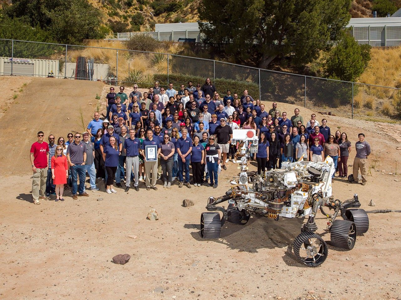
About 100 members of NASA’s Perseverance Mars rover mission team stand posed together in a sandy outdoor test facility alongside a full-scale Mars rover model.

PIA26813

Credits:
NASA/JPL-Caltech

Description

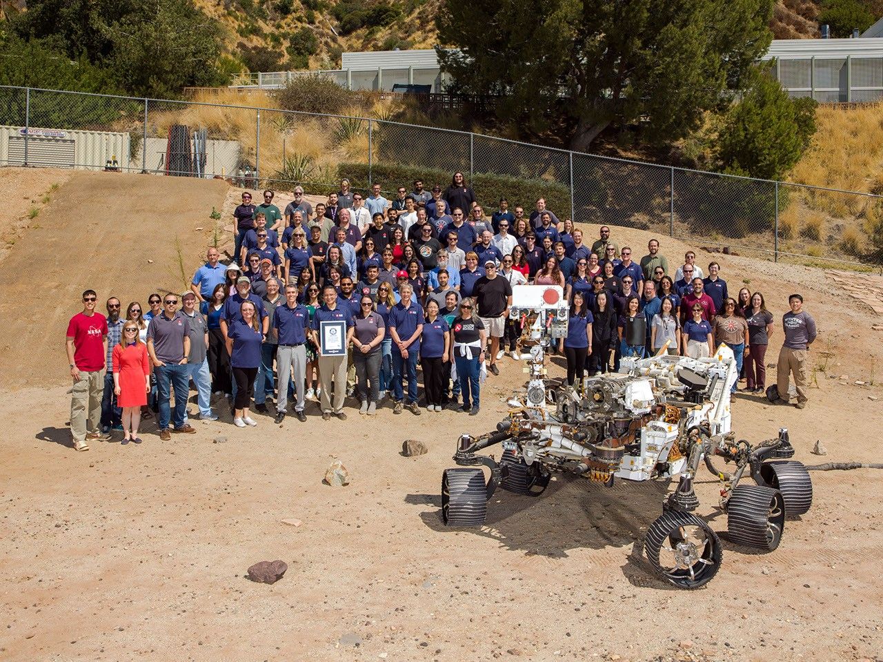
Members of NASA’s Perseverance Mars mission team gather in the Mars Yard at the agency’s Jet Propulsion Laboratory in Southern California with a certificate from Guinness World Records marking the rover distance record on the Red Planet. Positioned in front of the team is OPTIMISM (Operational Perseverance Twin for Integration of Mechanisms and Instruments Sent to Mars), a full-scale engineering model used to plan the rover’s driving routes and science activities on Mars. NASA JPL, which is managed by Caltech, built and manages operations of the Perseverance rover on behalf of the agency’s Science Mission Directorate in Washington, as part of NASA’s Mars Exploration Program portfolio.

For more about Perseverance: https://science.nasa.gov/mission/mars-2020-perseverance/

Source: science.nasa.gov

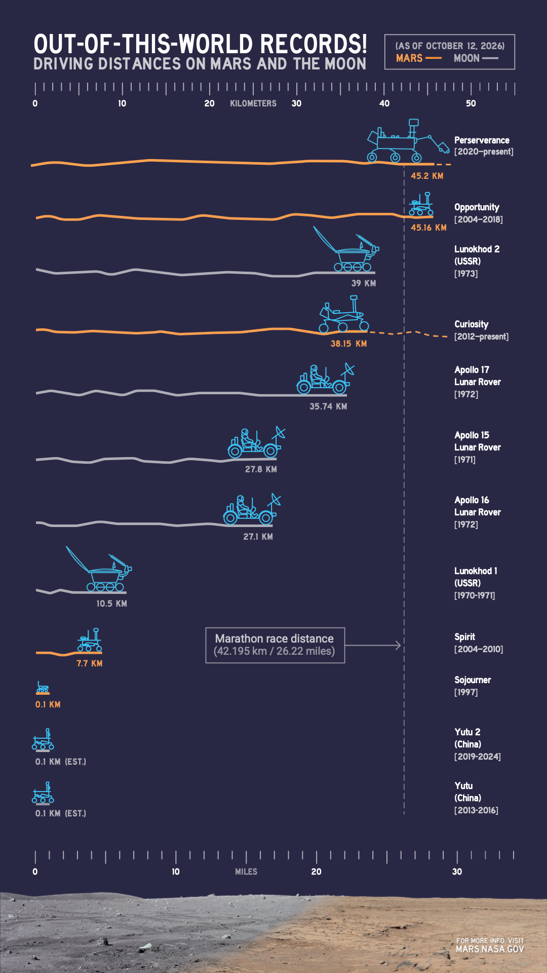
Comparing Off-World Rover Driving Distances

1 Min Read

Comparing Off-World Rover Driving Distances

An infographic compares driving distances on Mars and the Moon by various rovers, with NASA’s Perseverance leading as of Oct. 11, 2026, at more than 45 kilometers.

PIA26814

Credits:
NASA/JPL-Caltech

Description

This infographic illustrates the distances driven by various rovers on the surface of Earth’s Moon and Mars. Of the vehicles shown, the NASA Mars rovers Perseverance and Curiosity are still operational and moving across the surface; the figures shown for those two are distances driven as of Oct. 11, 2026. As of that date, Perseverance exceeded the distance record held by NASA’s Opportunity rover, which came to a final halt in 2018 at about 28.1 miles (45.16 kilometers) driven. 

NASA’s Jet Propulsion Laboratory, which is managed for NASA by Caltech in Pasadena, California, built and manages operations of the Perseverance rover on behalf of the agency’s Science Mission Directorate in Washington, as part of NASA’s Mars Exploration Program portfolio.

For more about Perseverance: https://science.nasa.gov/mission/mars-2020-perseverance/

Source: science.nasa.gov