NASA Opens New Flight Dynamics Research Facility in Virginia

Image of NASA Langley's Flight Dynamics Research Facility
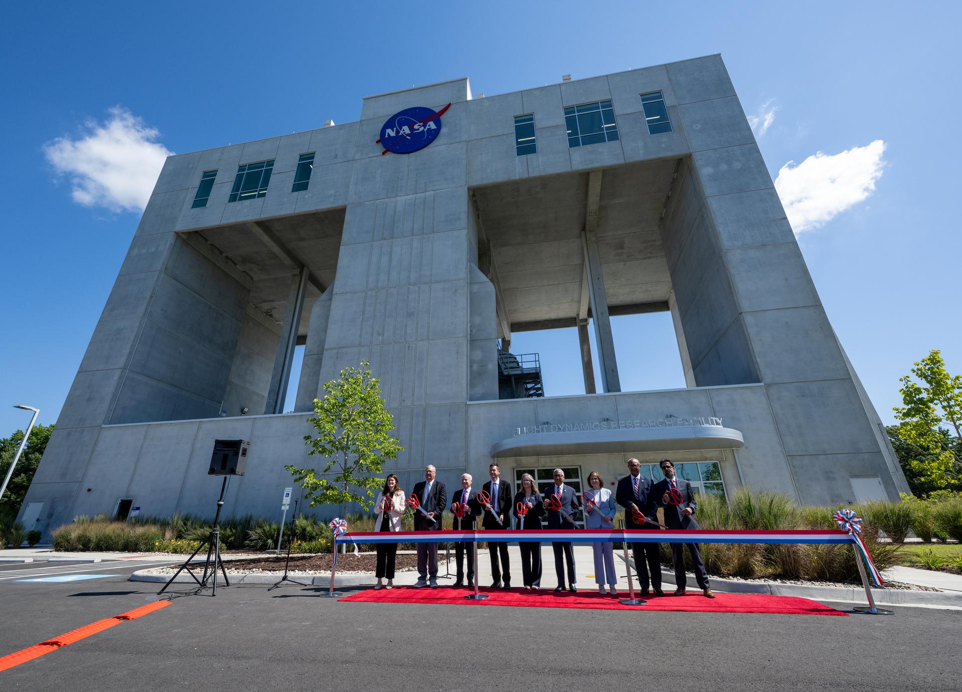
From left to right: Casey Swails, NASA deputy associate administrator; Mike Waller, vice president of BL Harbert International Federal Division; Edward C. Forst, administrator of the U.S. General Services Administration; NASA Administrator Jared Isaacman; Dr. Trina Dyal, director of NASA’s Langley Research Center; Rep. Robert “Bobby” Scott (D-Va.); Virginia Lt. Gov. Ghazala F. Hashmi; Jimmy Gray, mayor, City of Hampton; and Amit Kshatriya, NASA associate administrator, pose for a photo before cutting the ribbon to open the Flight Dynamics Research Facility, NASA’s newest wind tunnel, Friday, July 31, 2026, at NASA’s Langley Research Center in Hampton, Virginia.
Credit: NASA/Keegan Barber

NASA opened its newest wind tunnel, the Flight Dynamics Research Facility, Friday, providing a critical resource for the agency and its partners to test the safety and performance of future generations of aircraft, rockets, and space exploration vehicles.

Located at NASA’s Langley Research Center in Hampton, Virginia, the Flight Dynamics Research Facility will support advances in aircraft safety, X‑plane development, drone research, and spacecraft technology. The facility will enable both free‑flight and mounted testing of a wide range of scale-model vehicles designed to travel through an atmosphere, from airplanes to space capsules returning to Earth.

“The Flight Dynamics Research Facility is NASA’s first major new wind tunnel in more than 40 years and gives us a powerful new platform to test the ideas and technologies that will shape the future of aviation and exploration,” said NASA Administrator Jared Isaacman. “America has led in air and space because we were willing to take on hard problems, challenge assumptions, and build what didn’t exist before. This facility gives the talented team at Langley, and our partners across government, industry, and universities, the tools to keep pushing the boundaries of what’s possible and ensure America remains the world leader in air and space.”

A ribbon-cutting ceremony at NASA Langley marked the start of a new chapter in flight research. Agency leaders, partners, and Virginia officials emphasized how the Flight Dynamics Research Facility’s state-of-the-art capabilities will shape the future of flight and exploration.

“The opening of the Flight Dynamics Research Facility represents a significant advancement for NASA and for the nation,” said Dr. Trina Dyal, NASA Langley center director. “By bringing modernized testing capabilities under one roof, we are enabling transformative research that will ensure the United States remains at the forefront of aeronautics and exploration.”

Built through a partnership with the U.S. General Services Administration (GSA), the facility replaces aging infrastructure with an energy-efficient facility that reduces maintenance costs and provides the flexibility needed for future research. The Flight Dynamics Research Facility is part of a broader, long-term collaboration between the agencies, representing the fourth new building GSA has delivered to NASA under Langley’s 20-year campus revitalization plan.

“GSA is proud to partner with NASA in delivering the Flight Dynamics Research Facility, a state-of-the-art asset that will power the next generation of American dominance in aeronautics and space exploration,” said Edward C. Forst, GSA administrator. “This facility reflects what we do best: provide the advanced, expertly designed installations that federal agencies need to carry out their missions. With these new capabilities, NASA will be better equipped to test bold ideas, validate new designs, and advance technologies that will serve the nation for decades to come.”

The Flight Dynamics Research Facility combines and improves upon the capabilities of two historic NASA Langley wind tunnels – the 20-Foot Vertical Spin Tunnel and the 12-Foot Low-Speed Tunnel. The 25,000-square-foot building features a vertical wind tunnel with improved airflow, modern digital systems, and flexible testing capabilities that will allow researchers to study how aircraft, spacecraft, parachutes, and other vehicles behave during flight.

The facility’s 20-foot diameter test chamber is much larger than those of its NASA Langley predecessors, allowing for more air to pass around test models and improving data accuracy. Its increased size also allows for the use of larger, more detailed models during testing.

The Flight Dynamics Research Facility’s top airspeed of 117 miles per hour is twice as fast as the old  facilities, enabling free-flight tests of heavier scale models. This will allow simulations of full-scale vehicles flying at higher altitudes – a critical capability for operations such as studying the stability of aircraft or reentry capsules coming back from space.

The facility’s wind power comes from four 750-horsepower motors, each with an integrated, 14-foot diameter, eight-bladed fan. The fan blades are made of lightweight carbon fiber, enabling rapid, precise airspeed adjustments during free‑flight tests.

The Flight Dynamics Research Facility illustrates the powerful synergy between NASA’s aeronautics and space exploration efforts, with each driving innovation in the other. The facility will drive experimental research across a wide range of flight systems, advancing the development of autonomous flight vehicles, drones, commercial and military aircraft, and X‑planes.

As NASA prepares for a sustained human presence on the lunar surface through the Artemis program and the development of a Moon Base, the facility will play a key role in testing vehicle designs for entry, descent, and landing that will help reduce mission risk and support the safe return of crews to Earth. NASA also will be able to use the wind tunnel  to help design aircraft for Mars and other destinations in our solar system where atmospheric flight is possible.

With the Flight Dynamics Research Facility now open, NASA is entering a new era in flight research – one that will shape the aircraft and spacecraft of tomorrow, strengthen industry partnerships, and extend the agency’s legacy of pioneering aerospace leadership.

The facility is managed under the Aerosciences Evaluation and Test Capabilities portfolio in the Aeronautics Division of NASA’s Research and Technology Mission Directorate.

Learn more about the Flight Dynamics Research Facility at:

https://go.nasa.gov/4yzKEGQ

-end-

Camille Gallo / Rob Margetta
Headquarters, Washington
202-358-1600
[email protected] / [email protected] 

Kimiko Booker / Brittny McGraw
NASA Langley, Hampton, Virginia
757-506-5939 / 757-769-3763
[email protected] / [email protected]

Source: www.nasa.gov
NASA to Showcase Agency’s Newest Wind Tunnel in Virginia

Flight Dynamics Research Facility
The Flight Dynamics Research Facility, located at NASA’s Langley Research Center in Hampton, Virginia, is the agency’s first major wind tunnel built in more than 40 years.
NASA/Mark Knopp

Media are invited to NASA’s Langley Research Center in Hampton, Virginia, on Friday, July 31, to attend a media tour and ribbon-cutting ceremony for the Flight Dynamics Research Facility, the agency’s first new wind tunnel in more than 40 years.

The event will include a brief media availability with:

  • NASA Administrator Jared Isaacman
  • Dr. Trina Dyal, center director, NASA Langley
  • Administrator Edward C. Forst, U.S. General Services Administration

This event is in person only and open to members of the media who are United States citizens or lawful permanent residents. Information about timing will be shared closer to the event. NASA’s media accreditation policy is available online.

Media requesting to participate in person must RSVP no later than 5 p.m. EDT on Wednesday, July 29. Media RSVPs must be sent to Kimiko Booker, [email protected], and Brittny McGraw, [email protected], with the following information:

  • Legal first and last names (must match government identification)
  • Email
  • Phone number
  • Job title and organization

The wind tunnel opening marks a major milestone in the evolution of NASA and the nation’s aeronautics and space research capabilities. The state-of-the-art facility will support research and technology development that will advance NASA’s aeronautics, exploration, and science goals, including establishing a sustained human presence on the lunar surface through the Artemis program and the development of a Moon Base.

Learn more about the Flight Dynamics Research Facility at:

https://go.nasa.gov/4yzKEGQ

-end-

Camille Gallo / Rob Margetta
Headquarters, Washington
202-358-1600
[email protected] / [email protected] 

Kimiko Booker / Brittny McGraw
NASA Langley, Hampton, Va.
757-506-5939 / 757-769-3763
[email protected] / [email protected]

Details

Last Updated

Jul 22, 2026

Editor
Jennifer M. Dooren

Source: www.nasa.gov
NASA, GE Aerospace Work Enables Hybrid-Electric Flight Demonstration

4 min read

Preparations for Next Moonwalk Simulations Underway (and Underwater)

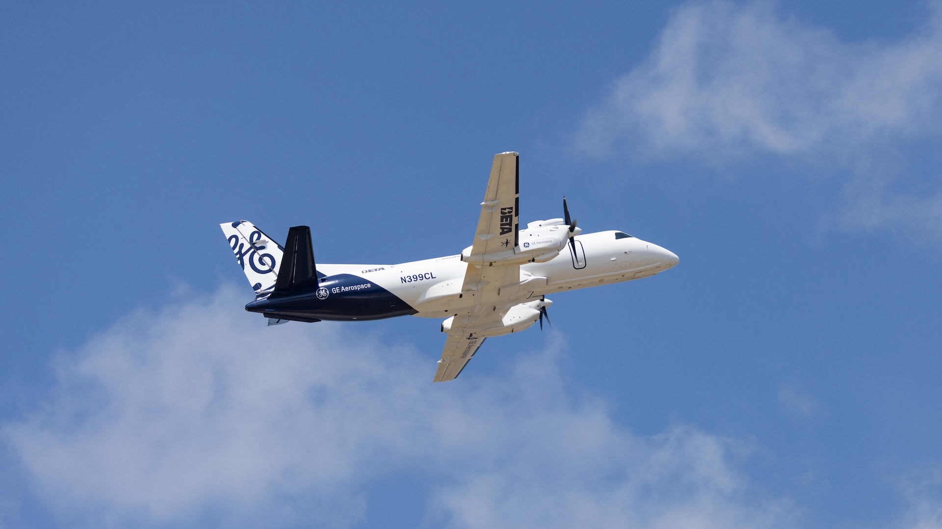
Modified Saab 340, a hybrid-electric aircraft in flight.
A modified Saab 340B aircraft in flight powered in part by a hybrid electric system built by GE Aerospace, along with NASA, BETA Technologies, and Boeing.
GE Aerospace

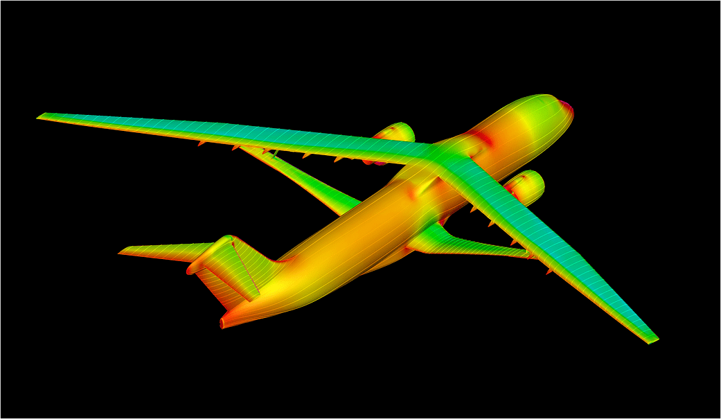
An aircraft powered by a megawatt-class hybrid-electric engine developed in collaboration with NASA and built by GE Aerospace, demonstrated flight of an innovation that can inform new generations of fuel-saving aircraft power systems.

Mounted to a Saab 340B aircraft, the engine flew at Farnborough International Air Show in the United Kingdom. It was the public debut of a system that has in recent months made historic test flights, becoming the first hybrid electric-powered aircraft to fly above 30,000 feet.

“This achievement reflects what NASA does best in aeronautics: we explore bold possibilities, validate them through rigorous research and testing, and work with industry to turn breakthrough ideas into technologies that bring real value for the American people,” said Laurie Grindle, director of the Aeronautics Division within the agency’s Research and Technology Mission Directorate at NASA Headquarters in Washington.

The testing leveraged work done through NASA’s former Electrified Powertrain Flight Demonstration project and the agency’s ongoing Subsonic Vehicle Technologies and Tools project – years of collaborative research that included key testing at NASA test facilities. 

The engine integrates electric motors, a gas turbine, and energy storage capabilities. It was designed to demonstrate the capacity to power an aircraft around the size of a regional-class jet, reducing fuel burn and costs without sacrificing performance. The unit’s technology and designs are expected to be used to help develop future hybrid systems that could lower airline operating costs. 

The demonstration flight came after years of rapid development for the technology. For NASA, it also validates work that stretches back to a time when hybrid aviation propulsion seemed almost beyond the horizon of possibility.

This achievement reflects what NASA does best in aeronautics: we explore bold possibilities, validate them through rigorous research and testing, and work with industry to turn breakthrough ideas into technologies that bring real value for the American people.

LAURIE A. GRINDLE

LAURIE A. GRINDLE

Director of the Aeronautics Division within the agency's Research and Technology Mission Directorate

“This is the culmination of more than 15 years of work, and we did that because it’s going to have an impact for aircraft that will help reduce energy use and help U.S. companies and the public,” said Ralph Jansen, aerospace engineer at NASA’s Glenn Research Center in Cleveland. “It’s about having a vision that no one believes can happen and then doing the work to define and execute the research and development needed to make it happen.”  

This accomplishment was possible because of the collaborative effort of hundreds of people working on Electrified Powertrain Flight Demonstration and Subsonic Vehicle Technologies and Tools projects across NASA centers, in conjunction with GE Aerospace and its partner companies.

Hybird-Electric Evolves

In recent years, aviation has seen a boom in small aircraft and drones powered by electrical systems drawing from batteries. But large passenger and cargo planes require complex engines capable of supplying massive amounts of power. So more than a decade ago when NASA began contemplating hybrid systems, just the possibility of using electric motors to supplement some energy was a daunting engineering challenge. 

NASA spent about seven years performing preliminary research, working with small businesses and other partners to consider technological obstacles and the potential commercial viability of hybrid systems. During that time, the agency addressed several barriers to implementation including the power, thermal, and battery technology, and the integration of the power system, engine, and aircraft.

Through the agency’s Electrified Powertrain Flight Demonstration award, GE Aerospace and NASA worked with researchers to develop lighter and more efficient power systems and shrink key components – sometimes dramatically. 

NASA and GE Aerospace also leveraged agency facilities and resources to further their research. In 2022, GE Aerospace tested an integrated version of its propulsion system at NASA’s Electric Aircraft Testbed at the agency’s Neil A. Armstrong Test Facility in Sandusky, Ohio. Testing allowed the system to operate in conditions simulating 45,000 feet in altitude, the range in which commercial single-aisle aircraft fly. 

The team added components, including electric motors, power converters, propellers, and a GE Aerospace commercial engine, followed by more ground tests and eventual flight tests. For the researchers who’d spent years on the concept, seeing the engine powering an aircraft in flight was a major step in a long journey.

“I’ve got to say, I was pretty touched seeing it fly. It was just awesome,” Jansen said.  “It’s just like a regular plane, which is probably the best thing of all.”

NASA’s current support for this research is through the Aeronautics Division of its Research and Technology Mission Directorate.

Source: www.nasa.gov
NASA Pushes New Wing Design to Find Structural Limits

3 Min Read

NASA Pushes New Wing Design to Find Structural Limits

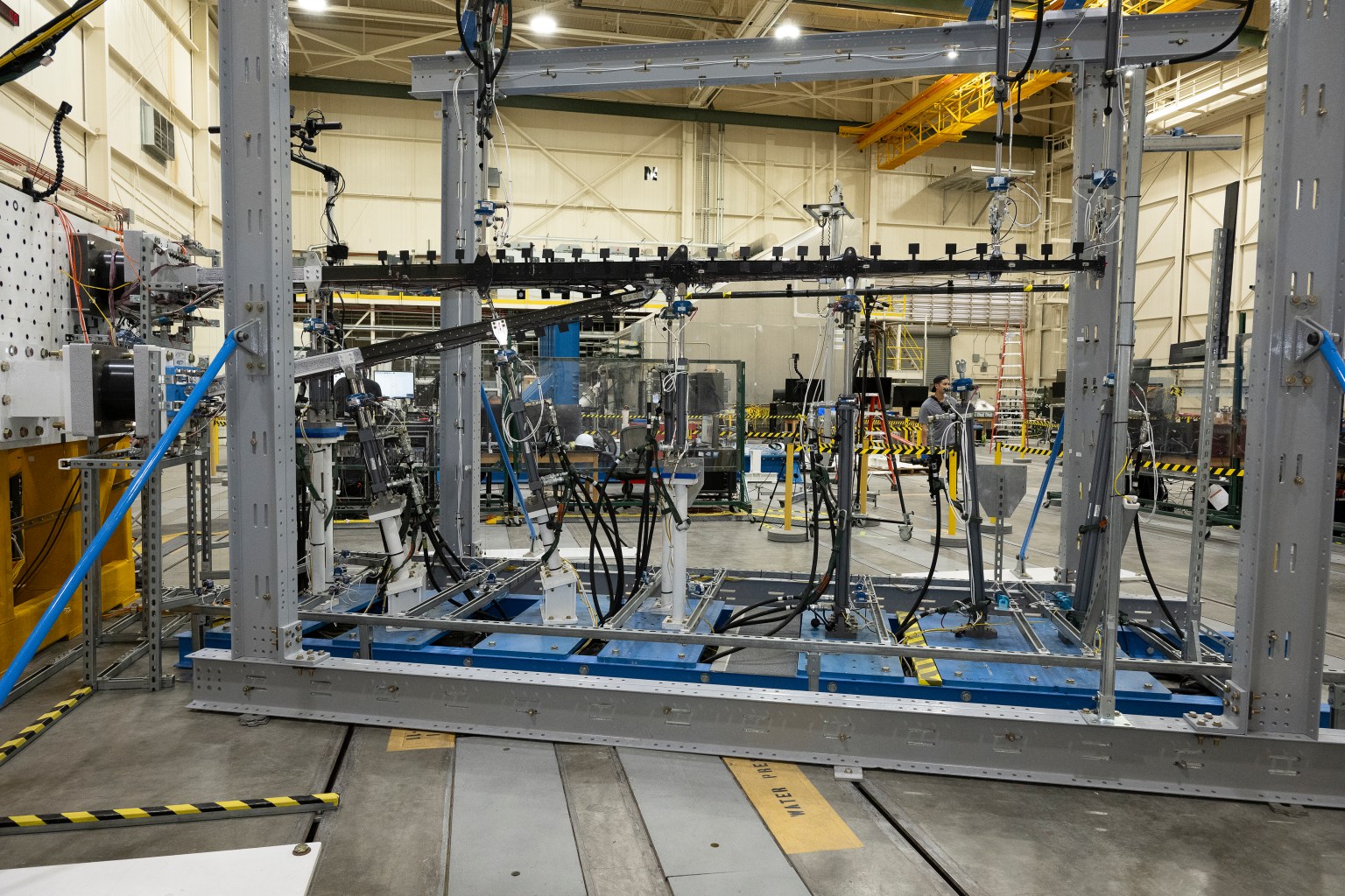
A wide view of a test structure in a laboratory shows a full test assembly secured inside a steel rig. Hydraulic lines, sensors, and support equipment surround the structure, with additional lab equipment visible in the background.

The 15-foot Structural Wing Experiment Evaluating Truss-bracing test article is fully installed in the Flight Loads Laboratory at NASA’s Armstrong Flight Research Center in Edwards, California, on Wednesday, May 20, 2026. The model is part of NASA’s research to develop technologies for future ultra-efficient aircraft.

Credits:
NASA/Carla Escamilla

NASA researchers recently put a new wing design, appearing long and thin with a lightweight structural design, through a series of grueling tests to find its structural limits. What they found left them encouraged about the wing’s potential, even when they pushed it past its intended limits.

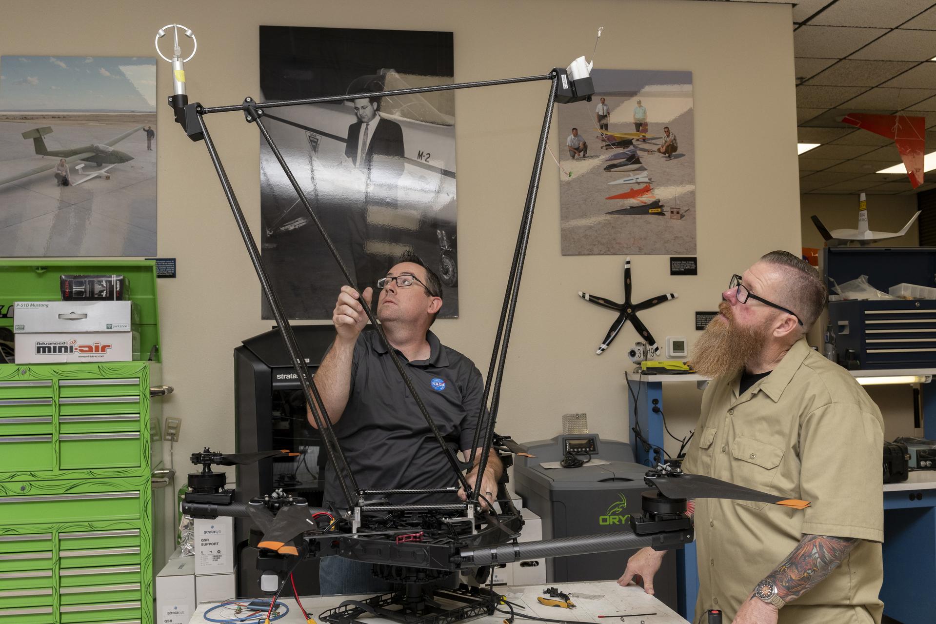
The 15-foot Structural Wing Experiment Evaluating Truss-bracing (SWEET-15) test article is part of NASA’s research to develop future ultra-efficient aircraft. The design incorporates a long wing supported by an aerodynamic strut, based on NASA’s earlier Transonic Truss‑Braced Wing concept.

The research team is working to understand whether SWEET-15’s design and its new lightweight structural designs could help commercial airliners save fuel. But first, they need to understand how it behaves under the kinds of force wings experience in flight.

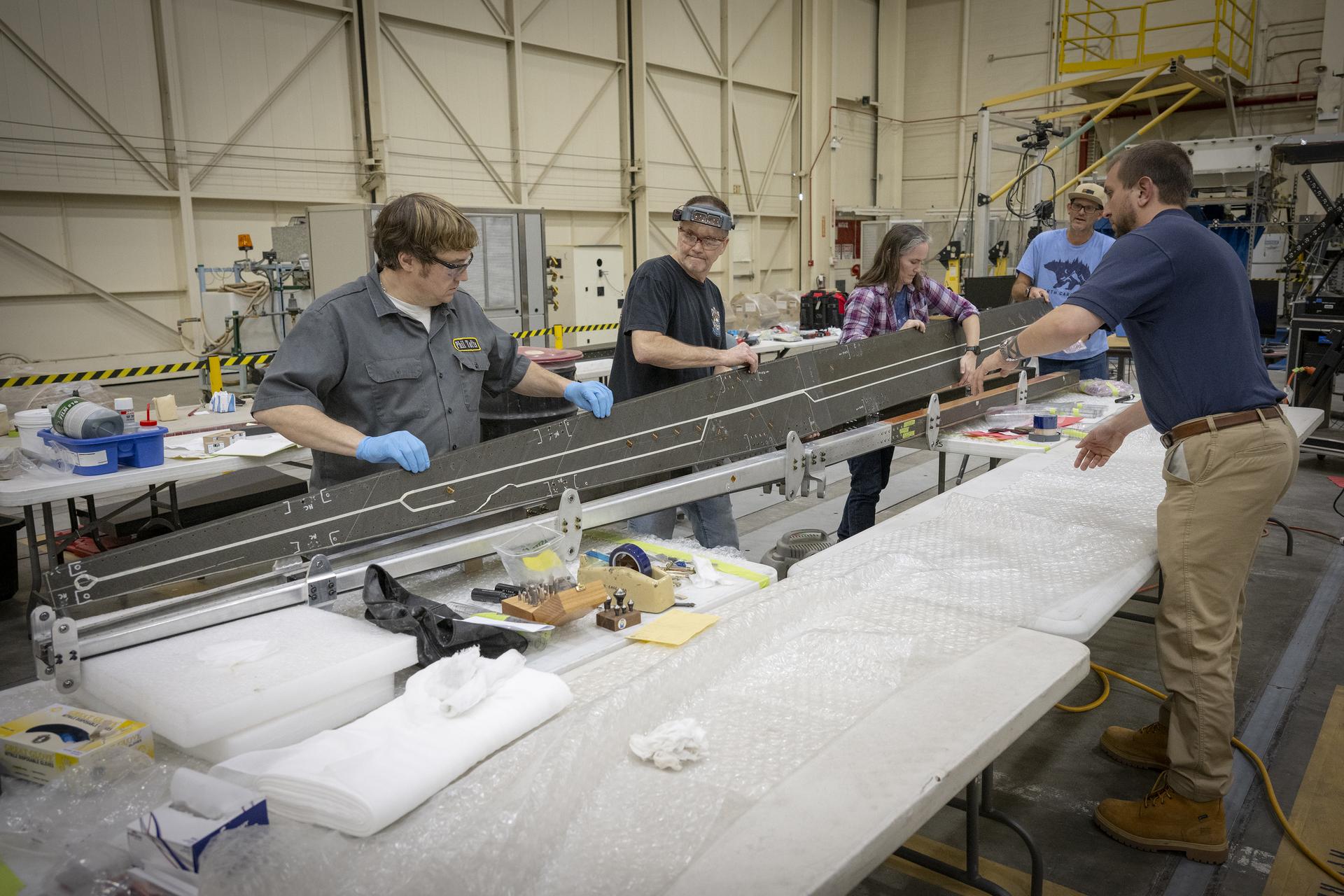
A group of people work together in a large workshop, handling and inspecting a long metallic structure laid across padded tables. Tools, materials, and protective equipment are spread across the workspace.
Lab technicians Phil Tofts, Chris McLain, and Jeff Howell and NASA engineers Erin Anderson and Richard Larson prepare the 15-foot Structural Wing Experiment Evaluating Truss-bracing model in the Flight Loads Laboratory at NASA’s Armstrong Flight Research Center in Edwards, California, on Thursday, Dec. 11, 2025. The model is part of NASA’s research to develop technologies for future ultra-efficient aircraft. 
NASA/Christopher LC Clark

The SWEET-15 design originated with combining five different advanced composite manufacturing and assembly technologies that enabled the novel structural design. The 15-foot-long test article was then designed and fabricated at NASA’s Langley Research Center in Hampton, Virginia, before traveling to NASA’s Armstrong Flight Research Center in Edwards, California, for testing.

Over several months, NASA engineers intentionally bent the test wing in the Flight Loads Laboratory at NASA Armstrong. Numerous strain and load sensors, including fiber-optic strain sensors, were placed throughout the structure to track how the wing responded as forces increased.

The data from the sensors confirmed the predictions made by NASA’s computer models. According to initial findings, the wing withstood the anticipated in-flight forces without issue. The results provided the team with confidence in the new manufacturing approaches and methods for connecting wing parts used in SWEET-15, which could support future efficient aircraft designs. The manufacturing approach, developed at NASA Langley used the Integrated Structural Assembly of Advanced Composites robot, aims to produce lighter and stronger composite structures for aerospace vehicles.

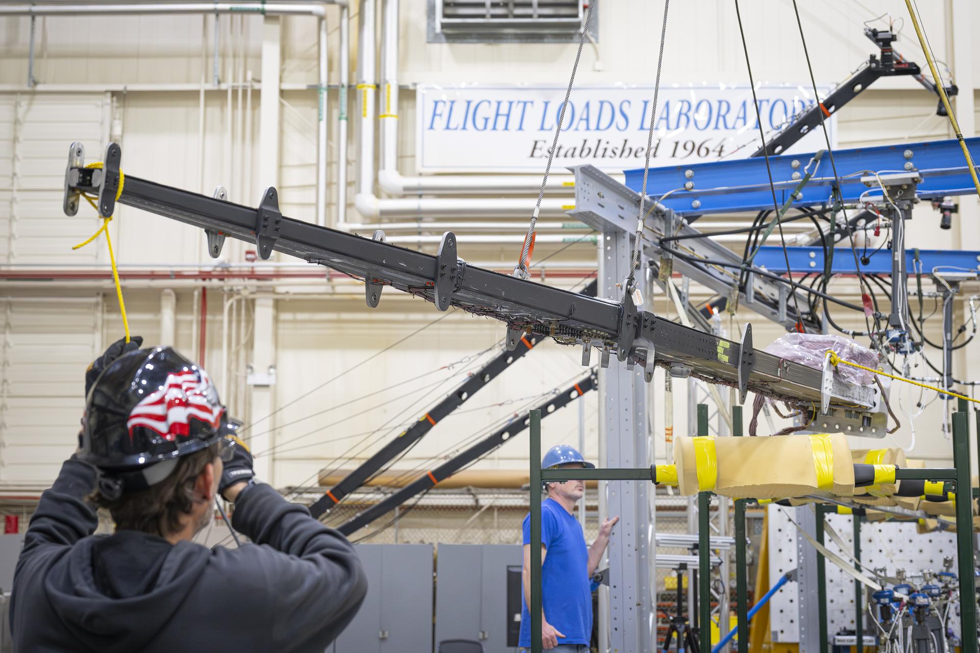
A long beam is suspended in a laboratory while personnel observe and guide its placement. Overhead support equipment, cables, and lab infrastructure surround the test area.
Lab technicians Jeff Howell, left and Chris Mount install the 15-foot Structural Wing Experiment Evaluating Truss-bracing model in the Flight Loads Lab at NASA’s Armstrong Flight Research Center in Edwards, California, Wednesday, February 11, 2026. The model is part of NASA’s research to develop technologies for future ultra-efficient aircraft.
NASA/Christopher LC Clark

The test concluded with a deliberate test-to-failure, where engineers increased loads beyond the wing’s design limits to determine how and where it would fail. The structure ultimately failed at roughly 127% of its design limit load, with visible damage appearing near the back edge of the wing and in the upper wing cover. This element of testing provided valuable insight into how the joints connecting the wing to its main strut and a secondary one, called a jury strut, behave under forces beyond the expected flight envelope.

This marks the first time a representative composite truss-braced wing configuration has undergone this type of structural evaluation.  It was made possible only through NASA collaboration across centers and projects, with researchers utilizing agency resources such as the Fiber Optic Sensing System developed to gather data on both aircraft and spacecraft.

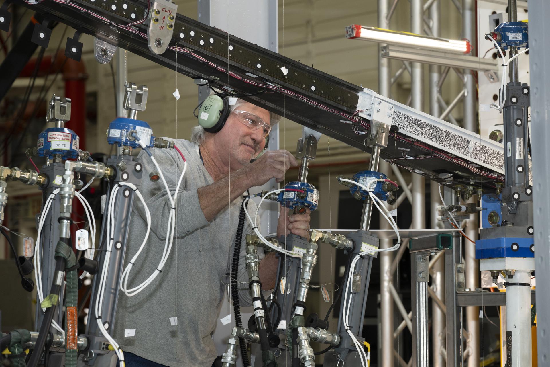
A man wearing ear protection works closely with multiple hydraulic and instrumentation units connected to a large beam mounted on a test structure. Numerous cables, hoses, and measurement devices extend from the setup.
NASA research engineer Walter Hargis regulates the 15-foot Structural Wing Experiment Evaluating Truss-bracing model in the Flight Loads Laboratory at NASA’s Armstrong Flight Research Center in Edwards, California, on Tuesday, March 31, 2026. The model is part of NASA’s research to develop technologies for future ultra-efficient aircraft. 
NASA/Ryan Kline

To prepare for the testing, engineers at NASA Langley designed, analyzed, and manufactured the wing and completed safety preparations and lab setup.

Researchers will now analyze the data collected during testing to inform future airframe designs and support NASA’s ongoing efforts to develop more efficient aviation technologies.

The work is being conducted through NASA’s Subsonic Flight Demonstrator project in the agency’s Research Technology Mission Directorate. The successful testing of multiple innovative components marks a milestone in NASA’s aeronautics research.

To learn more, visit:

https://www.nasa.gov/aeronautics/

Source: www.nasa.gov
NASA Uses Subscale Aircraft to Accelerate Flight Innovation

4 Min Read

NASA Uses Subscale Aircraft to Accelerate Flight Innovation

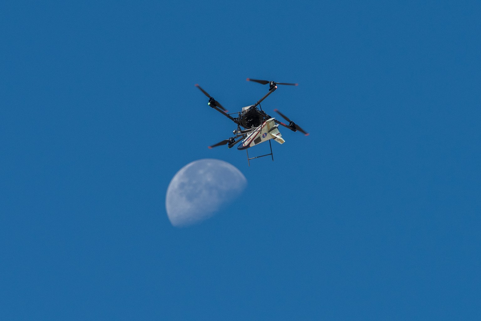
A white, blue, and red probe attached to a rotor with four blades flies in the blue sky, just above the Moon.

An atmospheric probe model attached upside down to a quad rotor remotely piloted aircraft ascends with the Moon visible on Oct. 22, 2024. The quad rotor aircraft released the probe above Rogers Dry Lake, a flight area adjacent NASA’s Armstrong Flight Research Center in Edwards, California. The probe was designed and built at the center.

Credits:
NASA/Steve Freeman

Testing new aerospace concepts in flight remains one of NASA’s most effective ways to advance knowledge and reduce risk.

The Dale Reed Subscale Flight Research Laboratory at NASA’s Armstrong Flight Research Center in Edwards, California, supports this mission by using small, remotely piloted and autonomous aircraft as cost‑effective platforms to mature innovative ideas, accelerate learning, and enable smoother transitions to full‑scale flight.

When experiments require a flight platform, several NASA remotely piloted aircraft are available: the Alta‑X quadrotor; the Dryden Remotely Operated Integrated Drone (DROID) with its 10‑foot wingspan; and the Multi‑Use Cub, a 14‑foot‑span fixed‑wing aircraft with an expandable payload capacity for flight experiments. For electric vertical takeoff and landing testing, the HQ‑90 quadrotor provides an additional option.

Once aircraft and experiments are cleared for operations, laboratory pilots support the mission, including ground operations and flight activities.

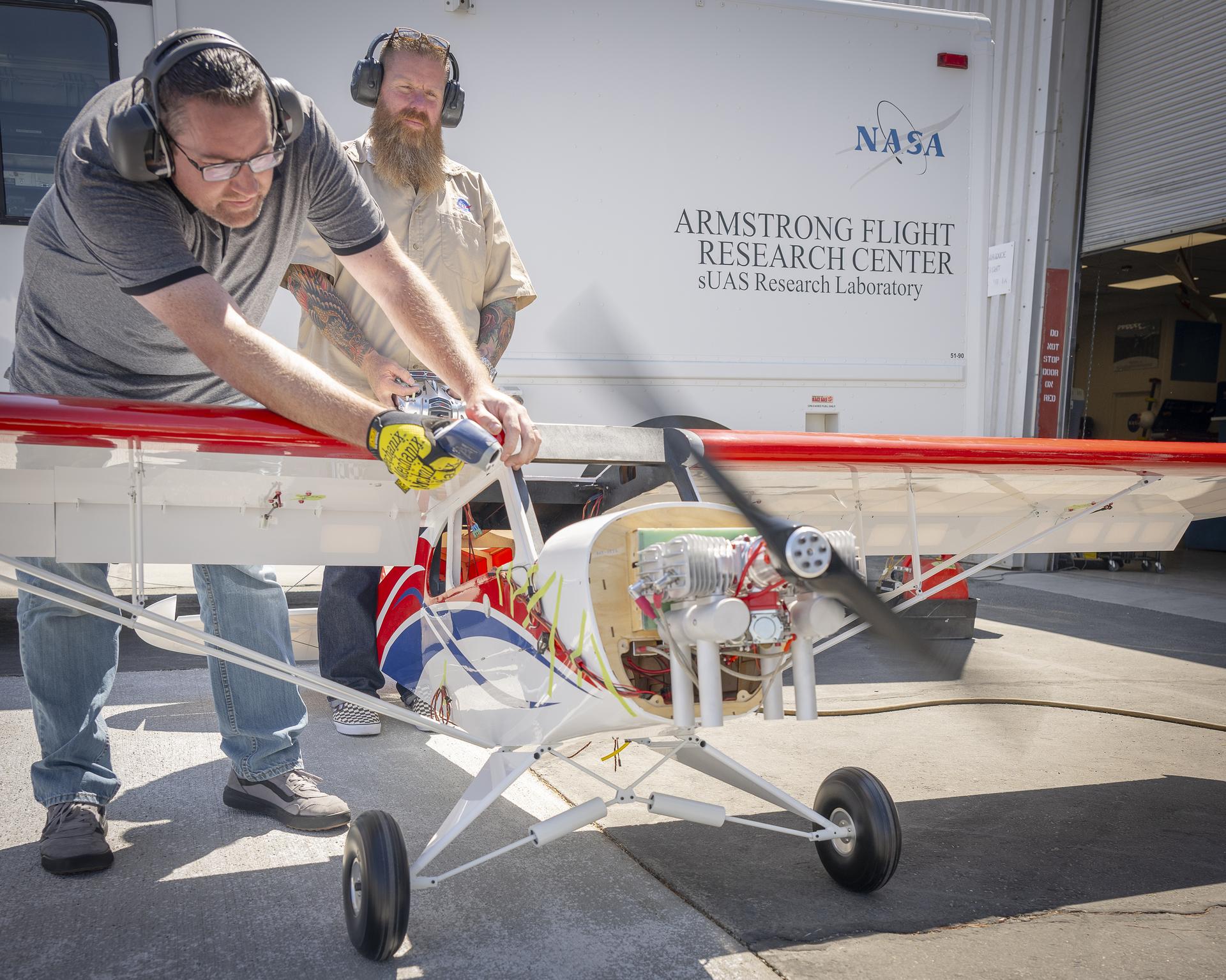
One man manages engine speed with a hand-held controller, while another firmly holds the subscale aircraft in place.
Justin Link, left, holds the subscale aircraft in place, while Justin Hall manages engine speed during preliminary engine tests on Friday, Sept. 12, 2025, at NASA’s Armstong Flight Research Center in Edwards, California. Link is a pilot for small uncrewed aircraft systems at the center’s Dale Reed Subscale Flight Research Laboratory and Hall is the chief pilot.
NASA/Christopher LC Clark

Flight expertise

Each staff member serves as an experienced and certified subscale aircraft pilot and is prepared to fly unique one-of-a-kind or modified commercial aircraft wherever the mission requires.

NASA’s FireSense project conducted flights in the Geneva State Forest, located about 100 miles south of Montgomery, Alabama. NASA Armstrong flight research staff integrated the instrument onto an Alta-X drone and tested the system before deployment. Two team members then transported the drone and sensor to the forest, prepared the vehicle for flight, and operated it during the mission. The NASA sensor was flown on the drone to demonstrate how remotely piloted aircraft can gather localized weather data that influences smoke movement and fire behavior. This information may help operational agencies improve wildfire decision-making and better allocate firefighters and resources.

Other missions occur closer to NASA Armstrong, such as the Enhancing Parachutes by Instrumenting the Canopy (EPIC) project. EPIC involved air‑launching a capsule containing a parachute and flexible sensor from the Alta‑X. Laboratory staff piloted the flights, supported flight operations, and worked with the EPIC team to design and integrate the parachute‑drop mechanism and safety system into the aircraft.

These tests demonstrated that a flexible sensor could help researchers study supersonic parachutes. Continuation of this work can help fill gaps in computer models, making supersonic parachutes safer and more reliable for delivering science instruments and payloads to Mars.

Two men integrate instruments onto a drone.
Justin Link, left, pilot for small uncrewed aircraft systems, and Justin Hall, chief pilot for small uncrewed aircraft systems, install weather instruments on NASA’s Alta X drone at the agency’s Armstrong Flight Research Center in Edwards, California. Members of the center’s Dale Reed Subscale Flight Research Laboratory used the Alta X to support the agency’s FireSense project in March 2025 for a prescribed burn in Geneva State Forest, which is about 100 miles south of Montgomery, Alabama.
NASA/Steve Freeman

Advancing challenging research

The Dale Reed Subscale Flight Research Laboratory uses rapid design and testing capabilities to help small aircraft fly big ideas. These concepts could lead to future breakthroughs that support NASA’s missions across aeronautics, science, and exploration.

For decades, NASA and its partners have advanced Automatic Collision Avoidance Technology. The research demonstrated an autopilot could detect and recover from an imminent ground collision – a capability now helping save lives in high‑performance U.S. military jets. NASA Armstrong had key roles in that work and developed a simplified version, the Automatic Ground Collision Avoidance System, which was installed on the DROID for testing.

The system demonstrated on the DROID — developed to assist general aviation pilots as well as remotely piloted and autonomous aircraft — performed well and led to further research toward a version that provides alerts and steering cues. The NASA Armstrong Technology Transfer Office is working to license the technology for U.S. businesses to develop the system as a commercial product.

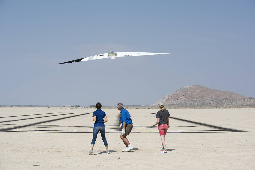
The Prandtl‑D (Preliminary Research Aerodynamic Design to Lower Drag) flying‑wing glider was also designed, fabricated, and flown at NASA Armstrong. Researchers found that its twisted wing design could reduce drag and generate thrust at the wingtips, advancing concepts that may support greater fuel economy for future aircraft. The original Prandtl‑D is now part of the Smithsonian National Air and Space Museum collection in Washington, and the Prandtl-D3 is at the California Science Center in Los Angeles. Researchers continue developing the next generation of the design in the laboratory.

A wide range of capabilities in the laboratory help transform promising concepts into flight-ready test structures. These include rapid prototyping using traditional and advanced 3D manufacturing techniques, as well as composite and conventional fabrication processes. The team of engineers and technicians also provides custom component design and specialized fabrication to meet unique research needs.

The laboratory supports electrical and mechanical design, hardware and software integration, and the safety and flight-readiness processes required for successful missions. Additional technical facilities, such as the Experimental Fabrication Branch and the Environmental Laboratory at NASA Armstrong, further enhance these capabilities. Together, they support development, testing, and validation activities that advance NASA’s aeronautics and exploration goals.

Deborah Jackson, Al Bowers and Abbigail Waddell successfully launch the subscale Prandtl-D 3C glider.
NASA

Details

Last Updated

Jul 15, 2026

Editor
Dede Dinius
Contact

Source: www.nasa.gov
Lala Batters Hawaii


August 16, 2026
August 15, 2026

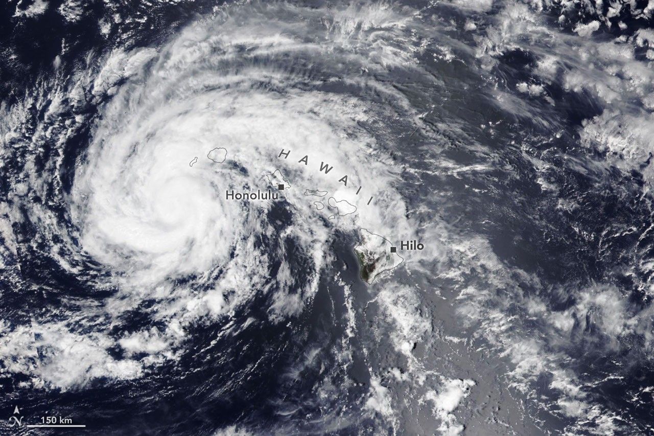
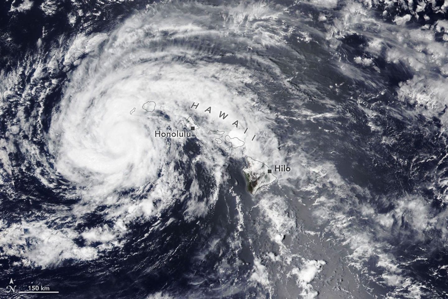
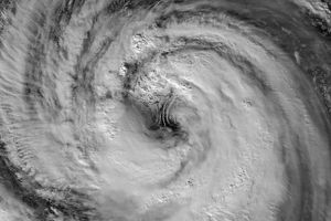
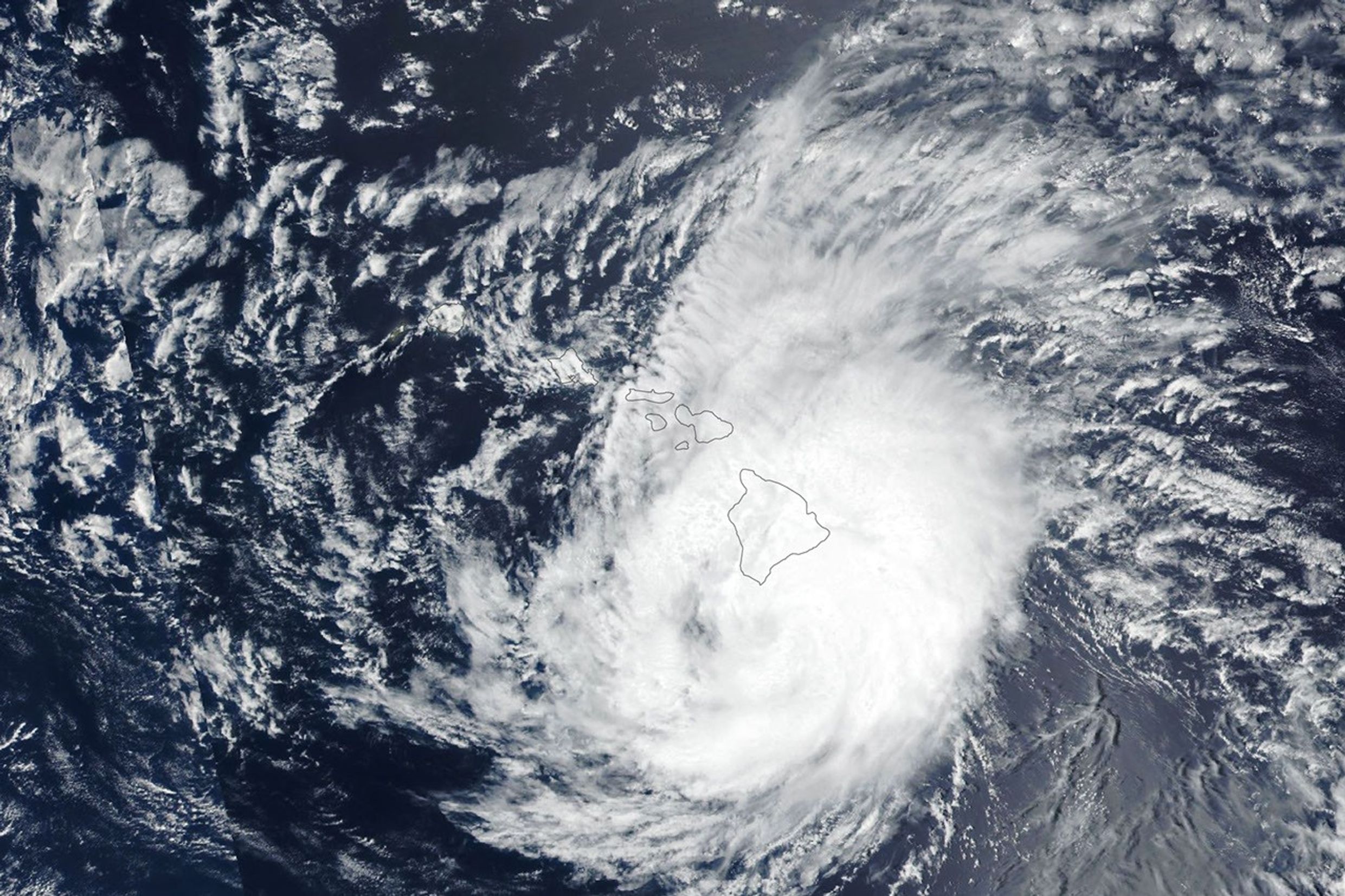
The spiraling clouds of a tropical storm are centered near the Hawaiian island of Kauaʻi.
NASA Earth Observatory / Lauren Dauphin

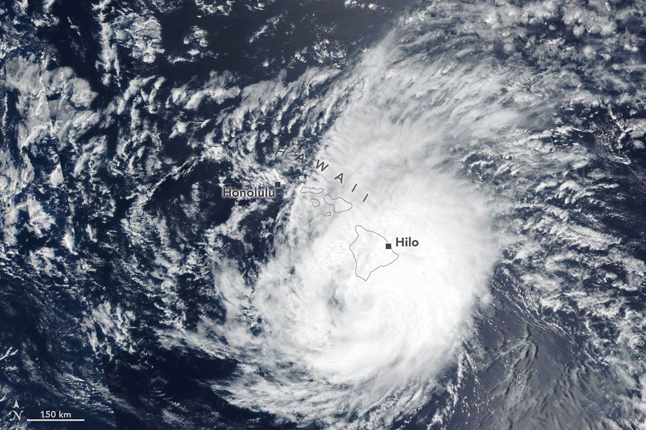
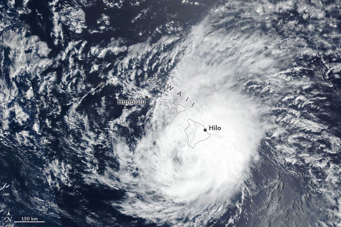
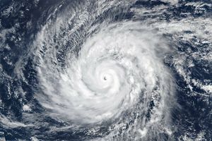
The spiraling clouds of a hurricane appear near the Hawaiian Islands. Its eye is just south of the Island of Hawaiʻi.
NASA Earth Observatory / Lauren Dauphin

The spiraling clouds of a tropical storm are centered near the Hawaiian island of Kauaʻi.
NASA Earth Observatory / Lauren Dauphin

The spiraling clouds of a hurricane appear near the Hawaiian Islands. Its eye is just south of the Island of Hawaiʻi.
NASA Earth Observatory / Lauren Dauphin


August 16, 2026

August 15, 2026


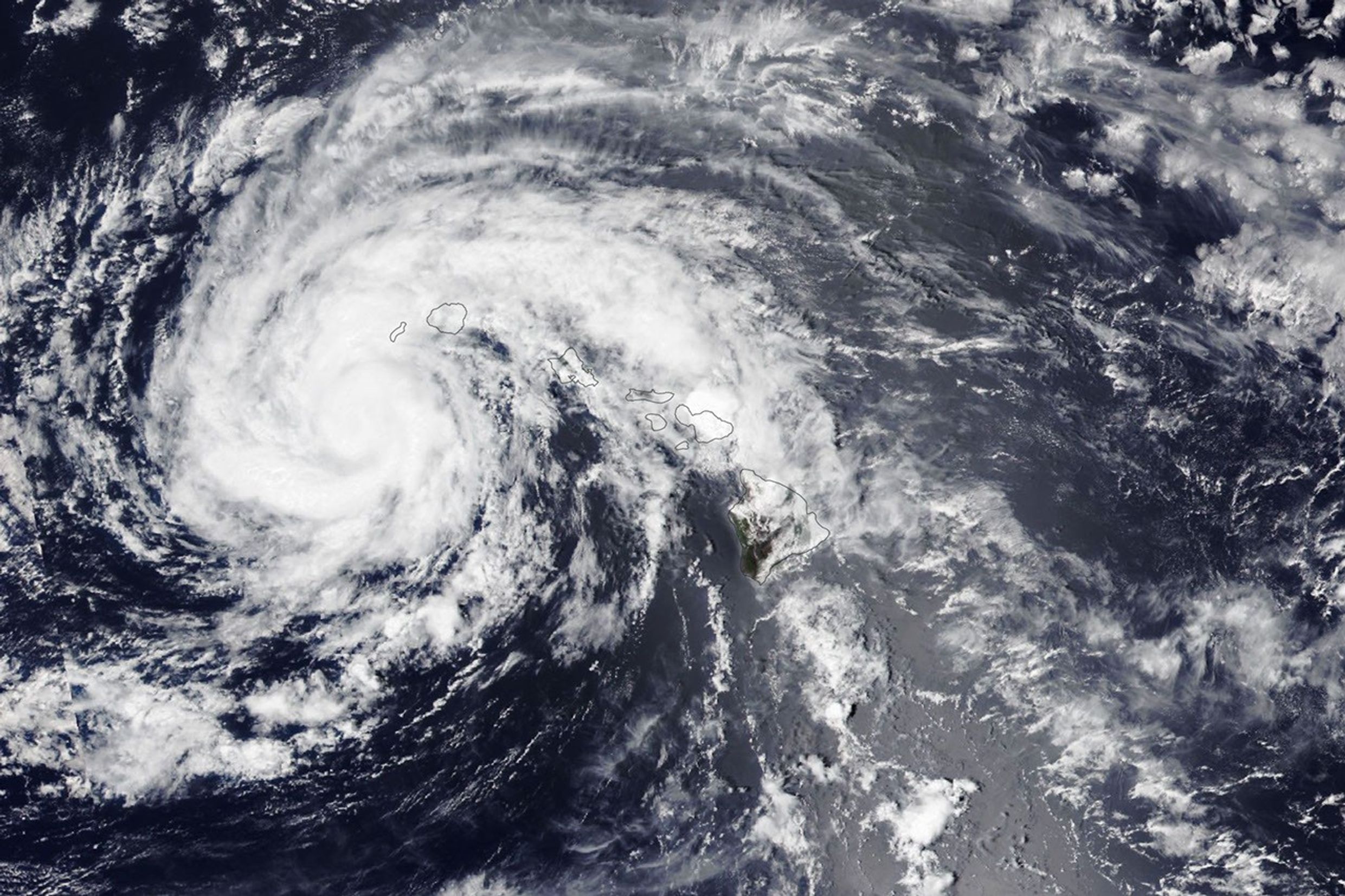
Lala skirts south of the Island of Hawaiʻi as a category 1 hurricane in the right image, acquired by the VIIRS (Visible Infrared Imaging Radiometer Suite) on the Suomi NPP satellite on August 15, 2026, at about 1:45 p.m. Hawaii Standard Time (23:45 Universal Time). The storm decreased in intensity while tracking northwest and was a tropical storm when the VIIRS on the NOAA-20 satellite captured the left image about 24 hours later. NASA Earth Observatory images by Lauren Dauphin.

The Island of Hawaiʻi narrowly avoided a direct landfall by Hurricane Lala in mid-August 2026. The storm nonetheless delivered serious damage as it passed just south of the island on August 15 (above, right) as a category 1 storm on the Saffir-Simpson wind scale.

Lala brought rainfall totals exceeding 20 inches (50 centimeters) to parts of the island, causing flash flooding and ongoing mudflow risks. The highest rainfall total for the storm—43.55 inches (110.6 centimeters) as of the morning of August 17—was recorded at Laupāhoehoe, on the coast northwest of Hilo. Lala downed trees, damaged bridges, and knocked homes off their foundations. Coastal areas were pummeled by large waves, while the summit of Mauna Kea, over 13,000 feet (4,000 meters) above sea level, experienced blizzard conditions.

By early afternoon on August 16, when the other image (left) was acquired, the storm had tracked northwest, roughly parallel to the island chain, and was southwest of Kauaʻi. Lala had decreased in intensity to a tropical storm, with sustained winds of 65 miles (105 kilometers) per hour, according to the National Hurricane Center.

While the Island of Hawaiʻi took the brunt of the storm, other islands also saw destructive effects. Strong winds caused widespread power outages, with more than 220,000 customers statewide without power as of the afternoon of August 16, according to news reports. Across the islands, wind and rain damaged infrastructure, and floodwaters and debris rendered roads impassable.

It has been an active tropical cyclone season in the Eastern Pacific so far in 2026, meteorologists note, consistent with what scientists expect during an El Niño, which has been underway as of mid-June. Warm water in the equatorial Pacific—the hallmark of El Niño—and the moisture and energy it transfers to the atmosphere help fuel nascent tropical storms. Lack of wind shear, another typical El Niño pattern in this region, also encourages tropical storms to develop and strengthen. The Atlantic hurricane season, in contrast, has been relatively calm, as greater wind shear over the Atlantic Ocean and Caribbean Sea during an El Niño inhibits hurricane formation by dissipating the upward motion of heat.

NASA Earth Observatory images by Lauren Dauphin, using VIIRS data from NASA EOSDIS LANCE, GIBS/Worldview, and the Joint Polar Satellite System (JPSS). Story by Lindsey Doermann.

References & Resources

You may also be interested in:

Stay up-to-date with the latest content from NASA as we explore the universe and discover more about our home planet.

Tropical Storm Arthur

2 min read

The first named storm of the 2026 Atlantic hurricane season brought intense rainfall and the threat of flash flooding to…

Article

Typhoon Jangmi

2 min read

The sprawling storm promised to deliver torrential rain across a wide swath of southern Japan.

Article

Super Typhoon Sinlaku

3 min read

The violent storm aimed at the U.S. Northern Mariana Islands and Guam in mid-April 2026.

Article

Source: science.nasa.gov

Chasing Fire Clouds in Utah


Natural Color
Brightness Temperature

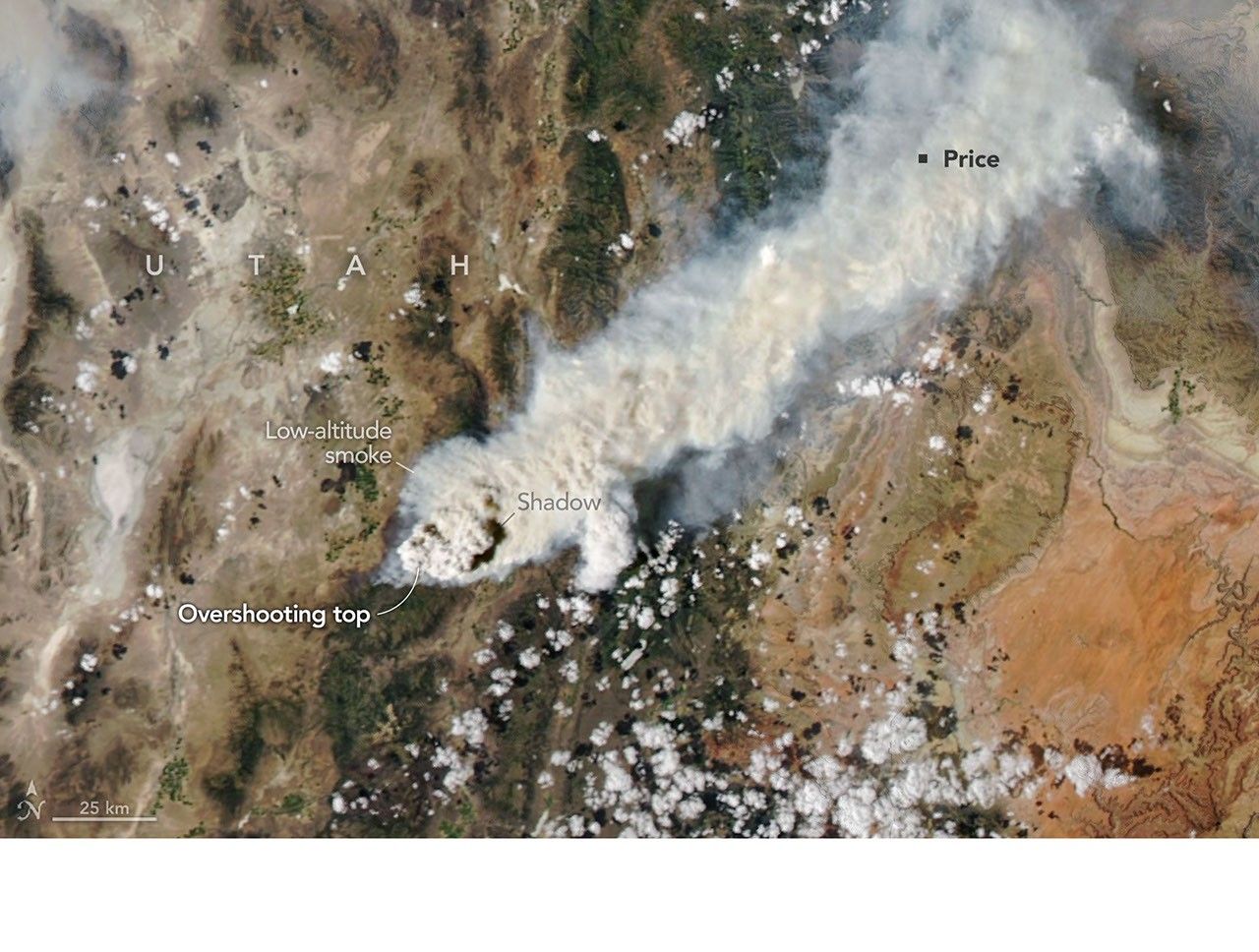
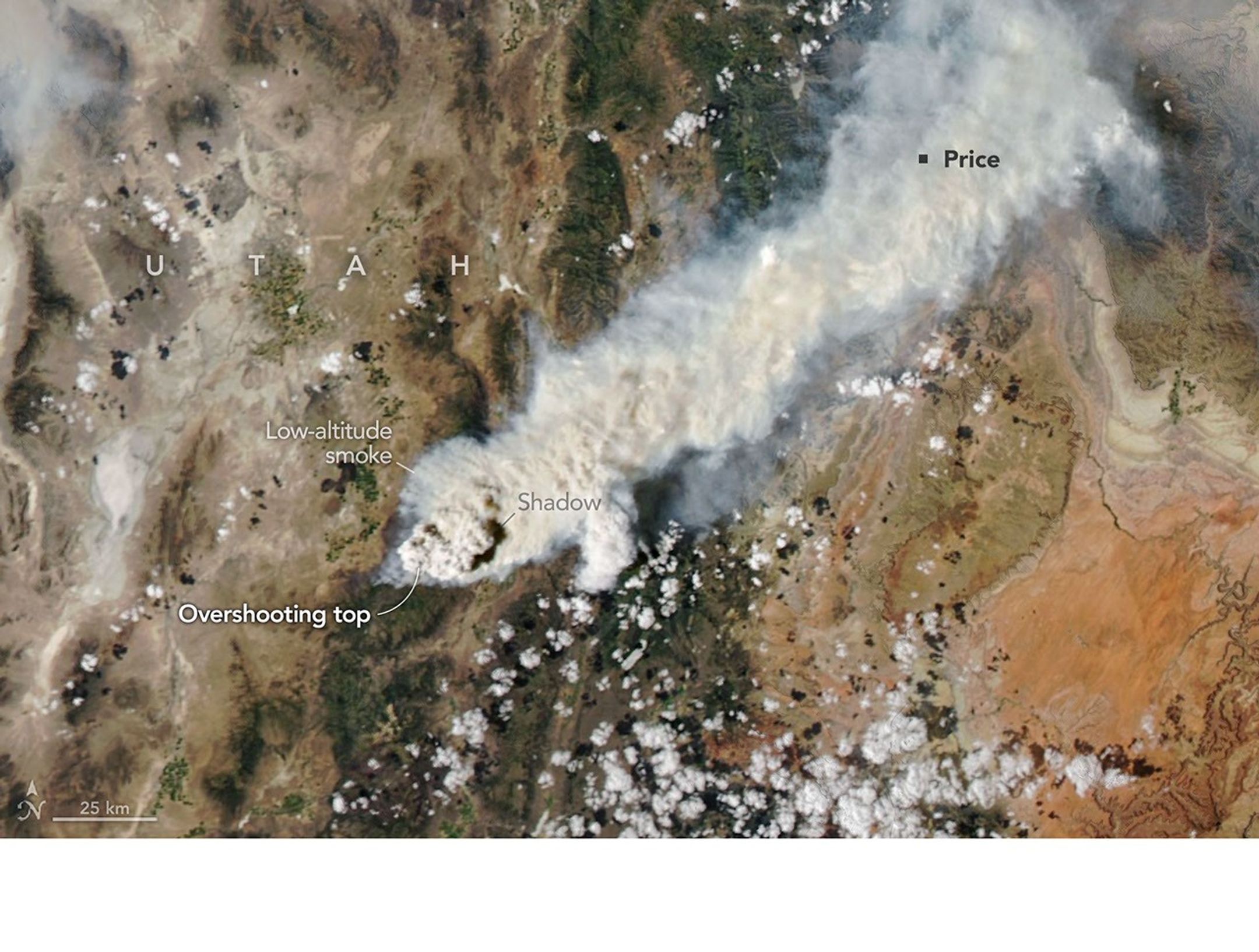
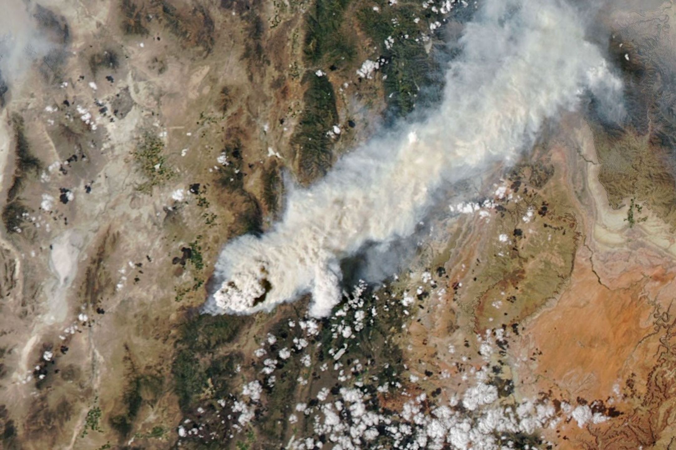
Textured gray wildfire smoke streams east from a fire burning near Fishlake National Forest. A dark shadow is visible to the east of a tall plume near the fire front.
NASA Earth Observatory/Michala Garrison

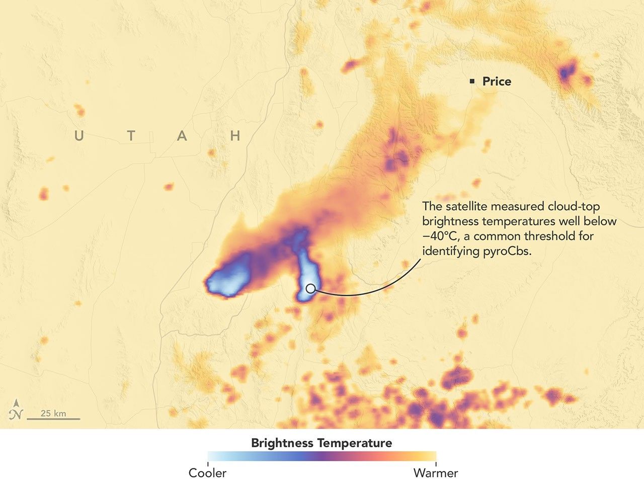
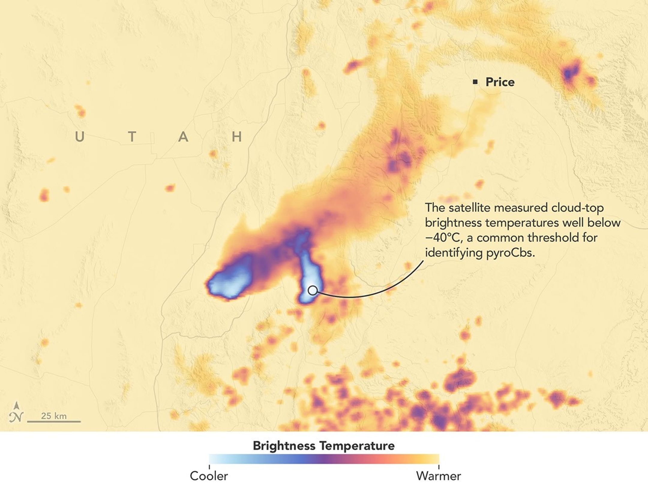
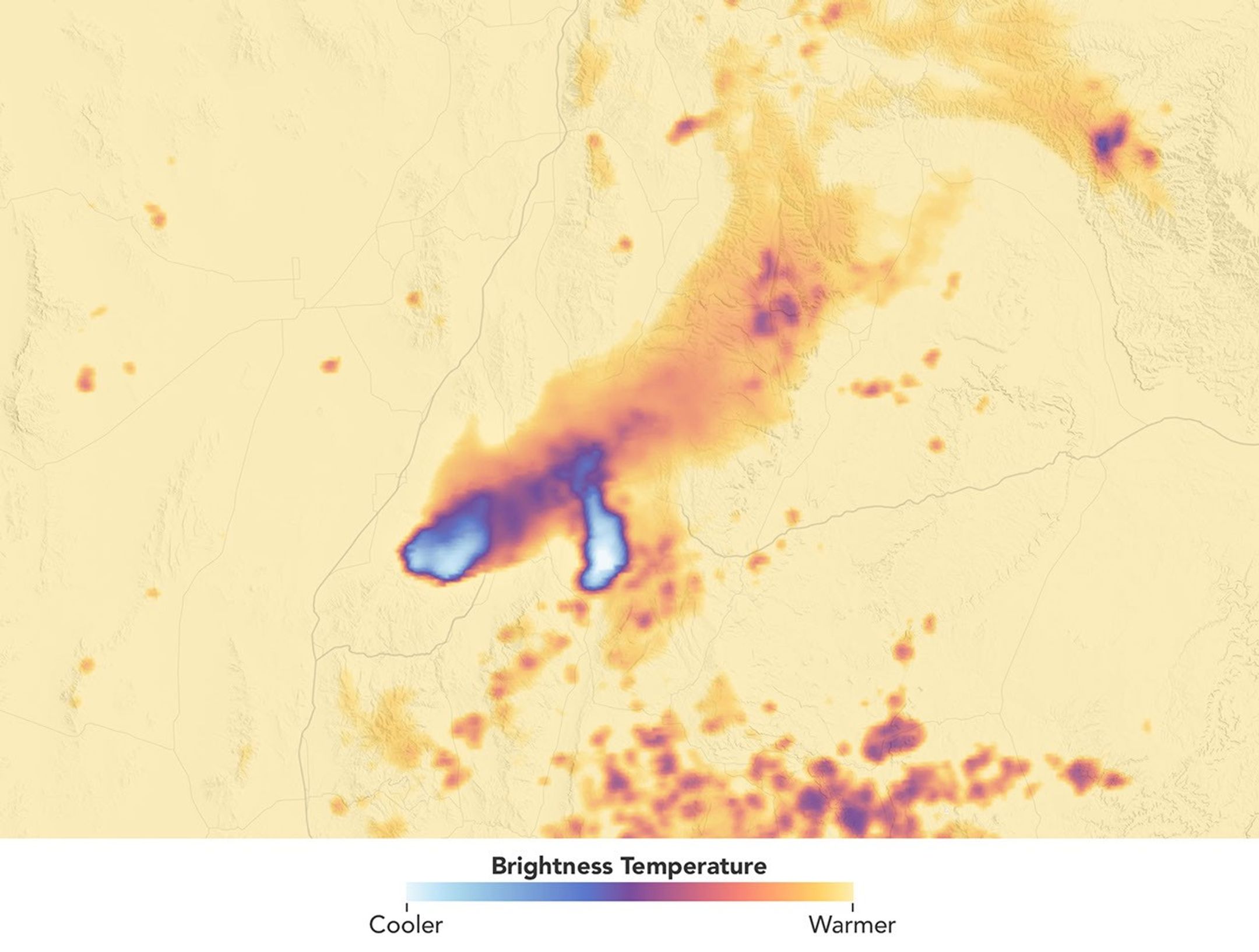
A data visualization shows the cloud-top brightness temperature of the same scene. Tall, cold smoky clouds appear white, and warmer plumes at lower heights appear purple.
NASA Earth Observatory/Michala Garrison


Natural Color

Brightness Temperature


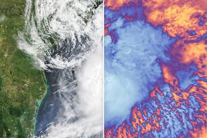
A smoke-infused pyrocumulonimbus (pyroCb) rises from the Widemouth 2 fire in Utah in these images captured by the MODIS (Moderate Resolution Imaging Spectroradiometer) on NASA’s Aqua satellite. The left image is natural color; the right image is false color, revealing cloud-top brightness temperatures below -40°C, a commonly used threshold for identifying pyroCbs. NASA Earth Observatory images by Michala Garrison.

Scientists have long known that volcanoes can launch large quantities of particles into the stratosphere. In the past few decades, it has become clear that wildfires do this, too, by generating towering, smoke-infused pyrocumulonimbus (pyroCb) clouds.

The largest pyroCbs are stunning weather-making features that generate massive thunderheads capable of unleashing lightning, hail, and heavy rain. A growing body of research shows that pyroCbs can also leave an outsized imprint on the upper atmosphere by channeling pulses of particles and gases into the stratosphere’s mostly dry, cloudless confines. Once there, smoke can spread widely and linger for months or years, sometimes circling the globe and likely influencing the ozone layer and Earth’s energy budget.

Understanding these enigmatic and dangerous clouds is why a team of atmospheric scientists—part of a NASA mission called INSPYRE (INjected Smoke and PYRocumulonimbus Experiment)—is spending the summer chasing them with NASA’s ER-2 aircraft, NSF/NCAR’s GV, and a suite of truck-based sensors. The team completed one of its first sampling runs of the summer on August 3, 2026, when the GV flew through a high-altitude pulse of smoke from the Widemouth 2 fire, one of Utah’s largest so far this year.

Lightning ignited the fire on July 27, 2026, but it remained relatively small until August 2, when it more than doubled in size amid intense winds and hot, dry conditions. That afternoon, soon after it had produced two pyroCb bursts, the MODIS (Moderate Resolution Imaging Spectroradiometer) on NASA’s Aqua satellite captured this image (above), showing a chimney of high-altitude cloud and smoke casting a shadow on low-altitude smoke below.

These bursts propelled clouds high enough that Aqua measured cloud-top brightness temperatures well below −40°C, a common threshold for identifying pyroCbs and a sign that the cloud tops were bubbling to the top of the troposphere and sometimes into the stratosphere. The brightness temperature measurements “reveal two discrete pulses of pyroCb action,” said Michael Fromm, a scientist at the U.S. Naval Research Laboratory. “The westernmost is the youngest pulse and stands out in the visible imagery by virtue of its shadow.”

Though relatively routine and minor, this pyroCb event followed a pre-dawn pyroCb from the same fire, imaged by the NOAA weather satellite GOES-West. “Morning pyroCbs are much more unusual,” Fromm said, because they don’t benefit from daytime heating that helps fuel convection. In this case, however, there appeared to be enough atmospheric instability and water vapor in the air to allow for pyroCb development. 

Multiple pyroCbs in a single day could have added unwanted complexity for forecasters and fire officials battling the blaze and organizing evacuations, said David Peterson, INSPYRE’s principal investigator. “Minimizing that sort of uncertainty for fire forecasters is a big part of the reason we’re out here studying this,” he added.

Remote sensing experts like Peterson and Fromm routinely study pyroCbs from afar with satellites, but it’s less common for pilots to chase and sample smoke plumes just hours after they form. In this case, the GV aircraft, on the ground in Colorado when the Widemouth 2 fire blew up, made a beeline for a high-altitude smoke plume as it drifted over New Mexico on August 3. The instruments on the plane sampled smoke at roughly 12 kilometers (8 miles) above the surface, collecting data at a height that isn’t typically incorporated into forecast models.

An aerial image shows a thick, puffy white cloud rising high above a patch of darker smoke visible near a surface of variable mountainous terrain.
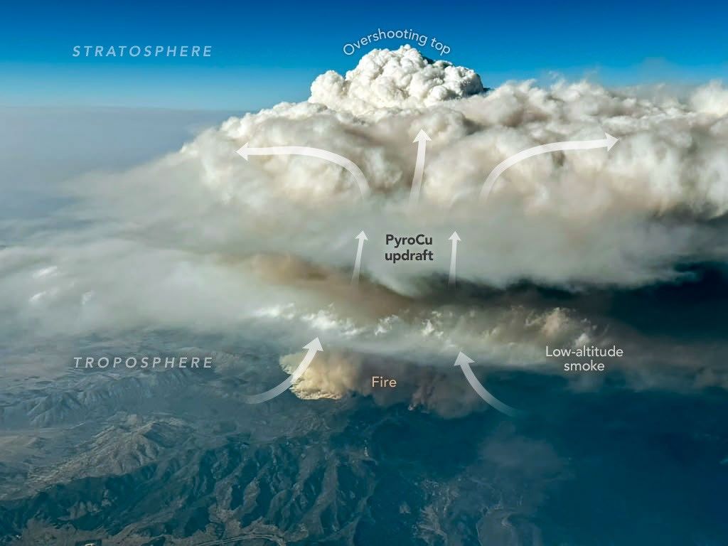
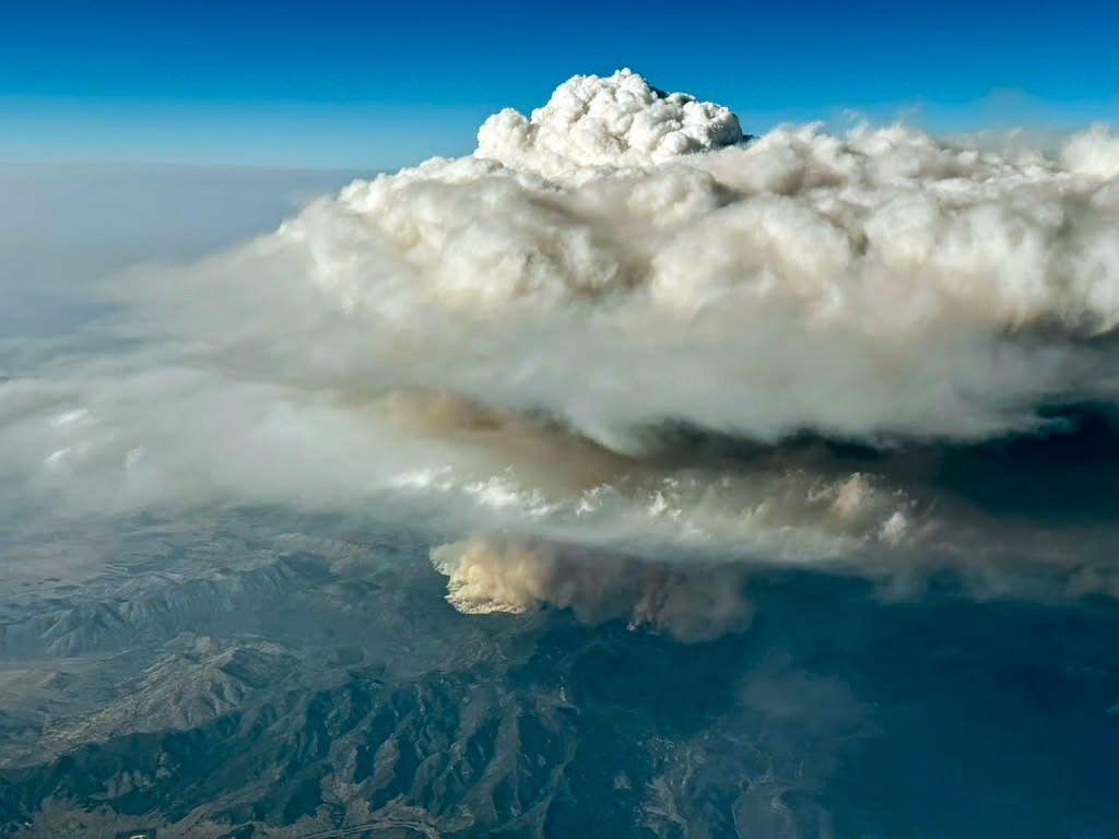
A photo of the Widemouth 2 fire taken from an INSPYRE aircraft during a sampling flight on August 3, 2026, shows a smoke-infused cloud rising high above the fire.
Bernadett Weinzierl/University of Vienna

During that mission, a scientist on board captured this image (above) of a pyrocumulus (pyroCu) billowing up over the Widemouth 2 fire. While not as tall or energetic as pyroCbs, pyroCus are precursor clouds that share many of the same characteristics. Here, heat from the fire is fueling strong convective updrafts, forming a towering cloud with puffy overshooting tops that poke into the upper troposphere as lower-altitude smoke drifts below.

Satellites excel at identifying pyroCbs by measuring the temperature of the cloud tops that form above smoke plumes. Using this technique, researchers have established that wildfires produce about 70 pyroCbs per year, many in dense forests of Canada and Russia, though plenty also occur in grasslands and savannas in the United States and Australia. So far in 2026, Fromm and colleagues have identified at least 13 in the continental United States.

Since one of the first pyroCbs appeared in the scientific literature in the early 2000s, scientists have cataloged well over 700 events, and they now believe that wildfires may contribute up to 25 percent of the black carbon and organic aerosols in the lower stratosphere. The sheer frequency of pyroCbs means that the total mass of particles they inject over the course of a wildfire season may rival that of large volcanic eruptions.

Still, many questions about the enigmatic clouds remain unanswered. It isn’t clear what vegetation is most likely to fuel pyroCbs, why some form more lightning than others, why they form in only a small fraction of fires, and how to accurately forecast them.

“Whether it be their dangerous manifestations on the ground or their long-lasting imprint on the upper troposphere and lower stratosphere,” Fromm said, “pyroCbs continue to surprise us.”

NASA Earth Observatory images by Michala Garrison, using MODIS data from NASA EOSDIS LANCE and GIBS/Worldview. Photo by Bernadett Weinzierl/University of Vienna. Story by Adam Voiland.

References & Resources

You may also be interested in:

Stay up-to-date with the latest content from NASA as we explore the universe and discover more about our home planet.

Cottonwood Fire Chars Utah

5 min read

The blaze burned more than 150 square miles and swept through parts of a ski resort.

Article

Ontario Wildfire Smoke Moves East

3 min read

Canadian wildfires sent plumes of smoke streaming over Ontario, Quebec, and parts of the U.S. Midwest and Northeast.

Article

Cascade Volcanoes Shrouded in Smoke

3 min read

From the International Space Station, astronauts photographed Mount Hood and Mount Rainier as wildfire smoke spread across the Pacific Northwest…

Article

Source: science.nasa.gov

NASA Data Helps Commercial Space Plan Living Off Our Moon 

3 min read

Preparations for Next Moonwalk Simulations Underway (and Underwater)

A multicolored picture of Earth's Moon.
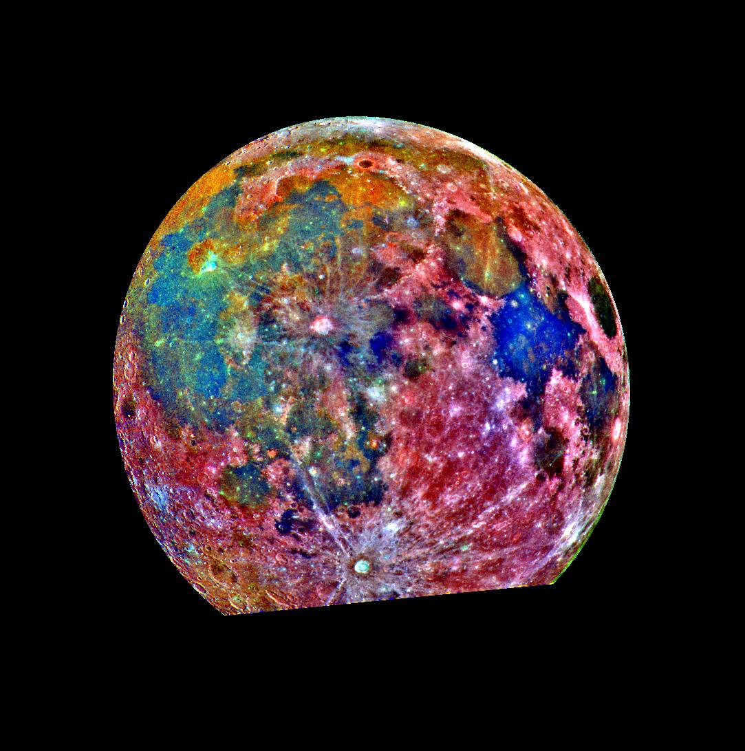
NASA has been taking pictures of the Moon for decades, collecting a wealth of data. This false-color picture is a composite of 15 images of the Moon taken through three color filters on NASA’s Galileo solid-state imaging system.
Credit: NASA

The barren lunar landscape has some important resources, such as water and minerals like iron and titanium, but extracting and processing them will require special equipment. Where those resources can be found will dictate where to land and how to mine them. To help with that, Lunar Station Corp. is using a wealth of NASA data in multiple computer models.

“With 60 years of lunar data available to us, we help our clients understand the environmental factors for any given location on the Moon,” said Blair DeWitt, CEO of Lunar Station. Combining disparate data from different sensors used by NASA and other space agencies is a critical first step. One NASA resource the Cambridge, Massachusetts-based company used to build terrain maps is the Ames Stereo Pipeline. The open-source code automatically processes images captured from satellites, robotic rovers, historical images, and more to create a 3D model revealing features such as rock placement and elevation.

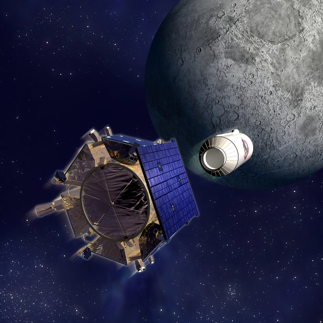
But the availability of in-situ lunar water resources at any location is largely unknown, according to Gerry Sanders, in-situ resource utilization system capability lead at NASA’s Johnson Space Center in Houston. To begin to fill that gap, the Lunar Crater Observation and Sensing Satellite was designed to crash its uppers stage into the Moon’s South Pole in 2009. The examination of the resulting plume revealed the presence of water ice.

Lunar Station is building on that work and more to help commercial space companies with mission planning, which includes scientific research for mining operations. The MoonHacker program uses proprietary geospatial analytics platform and advanced algorithms to fuse all the lunar data in NASA’s Planetary Data System to help identify indicators for shallow pits of lunar water.

“We can find sites for landing pads, for cultivating the best paths for roving, and inform our clients about communications. If you can’t see Earth at a given location like in the polar regions or the far side of the Moon, you have to come up with a relay strategy,” said DeWitt. “We can do this in part thanks to NASA data.”

In MoonHacker’s Radiation Simulator, an electronic version of a company’s rover or satellite, called a digital twin, can be subjected to the radiation en route or at the mission site to determine the protection required.

These innovations exemplify the purpose of NASA’s Technology Transfer program within the Research and Technology Mission Directorate, which uses space-based solutions to improve life on Earth. For 50 years, NASA has documented the everyday benefits of space technology through the agency’s Spinoff publication. 

Details

Last Updated

Aug 12, 2026

Source: www.nasa.gov
NASA Completes Astronaut-Deployed Science Instrument for Lunar Surface

Rectangular box-shaped device resting on a metal table. The front face is covered with a grid of many small black rectangular panels bordered in white. Metal components, brackets, and small box units are mounted along the top. The background shows a large windowed wall with a blurred American flag and an Artemis flag visible behind the device.
The fully-integrated LEMS (Lunar Environment Monitoring Station) ready for environmental testing. A small suitcase-size instrument suite built at NASA Goddard, LEMS is designed to carry out continuous, long-term monitoring of the seismic environment at the Moon, including surface motion caused by moonquakes and meteorite impacts in the lunar south polar region.
NASA Goddard/Mike Guinto

NASA has declared “wrenches down” on the first completed payload designed for Artemis astronauts to deploy on the Moon’s surface. Engineers working on NASA’s Lunar Environment Monitoring Station, or LEMS, have completed hardware development and testing and the payload is ready for its permanent home near the lunar South Pole. With the hardware complete, LEMS is ready to support one of the Artemis program’s core goals: enabling sustained lunar science and exploration.

The LEMS instrument package contains two highly sensitive seismometers that will monitor ground vibrations from moonquakes and meteorite impacts, providing scientists with insights into the Moon’s interior and the seismic hazards astronauts might encounter at the surface. Its modular design allows the system to be adapted or expanded to host new instruments in the future, creating a reusable platform that can evolve as scientific priorities grow.

The payload will remain in a clean room at NASA’s Goddard Space Flight Center in Greenbelt, Maryland, where it was built, until it is assigned to an Artemis mission for deployment to the lunar surface.

“The completion of the LEMS scientific instrument is a major step in a new era of lunar surface science. Innovative science experiments will uncover, measure, and reveal the Moon’s secrets while astronauts open new frontiers for discovery,” said Joel Kearns, deputy associate administrator for exploration, Science Mission Directorate, NASA Headquarters in Washington. “And, behind the scenes, countless teams across NASA and our partners are pushing the boundaries of what surface instruments can do, building the tools that will make future exploration possible and safer.”

An astronaut in a white spacesuit kneels in simulated lunar soil while working with scientific equipment in a large testing facility. Staff members and support structures are visible in the background.
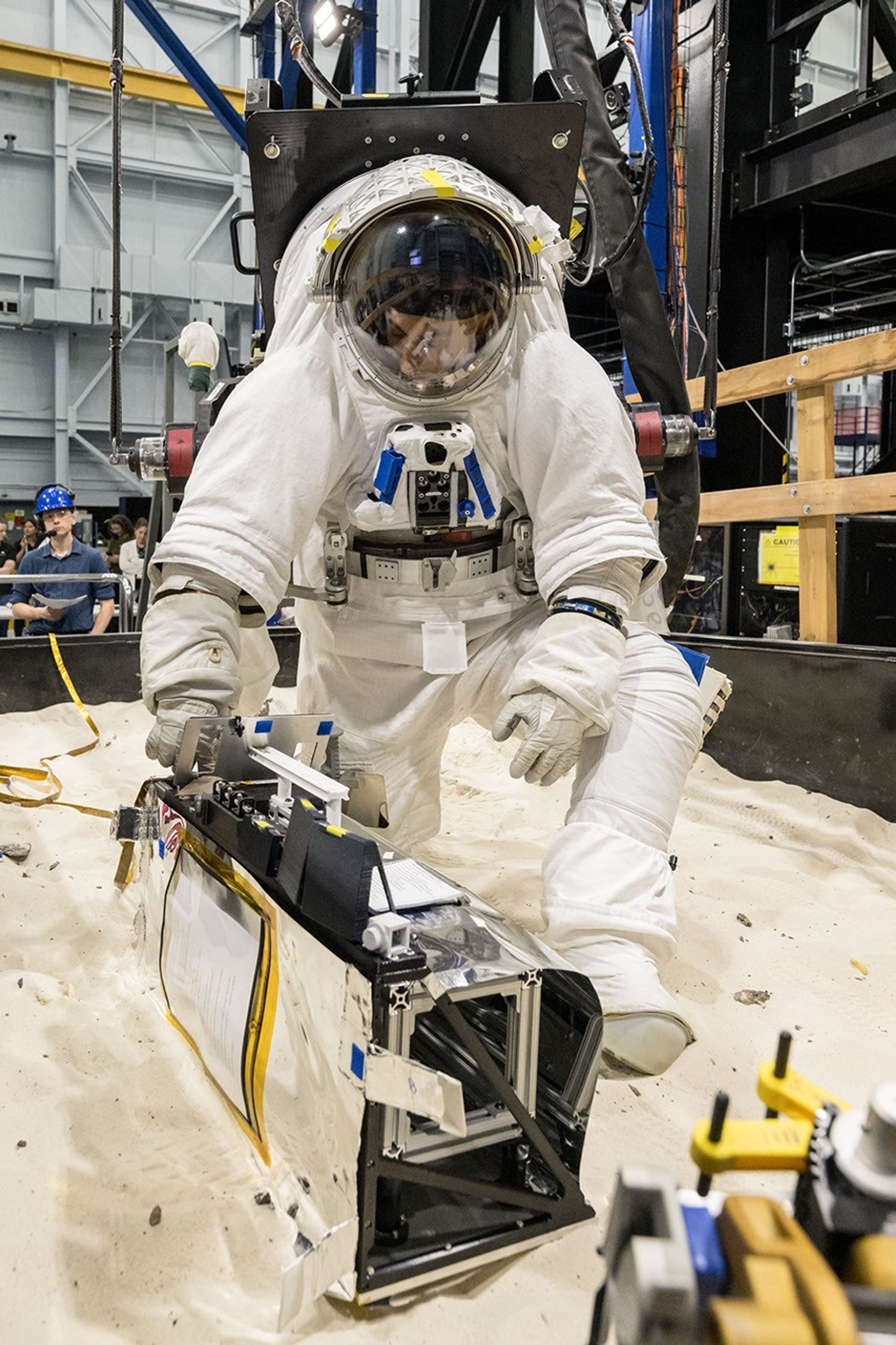
A scientist wearing NASA’s xEMU prototype space suit is testing the handling of a mockup version of NASA’s Lunar Environment Monitoring Station, or LEMS. The testing took place at the Active Response Gravity Offload System, a simulated reduced gravity environment at NASA’s Johnson Space Center in Houston.
NASA Johnson

The LEMS payload builds on a legacy of lunar seismic tracking. Apollo astronauts deployed a network of seismometers on the Moon’s nearside equatorial region between 1969 and 1972. Those instruments operated until 1977, recording about 13,000 moonquakes and other ground vibrations that helped scientists begin to understand the composition of the Moon’s interior. For decades, researchers have hoped to spread more seismometers, updated with new technologies, across the lunar surface.

Now, LEMS will carry the first seismometers to be deployed by future astronauts to listen for faint ground vibrations, collecting new clues to the Moon’s internal structure and ongoing seismic activity. The sensors will be the most compact, sensitive, and energy-efficient seismometers ever built for planetary exploration.

LEMS itself is about the size of a small suitcase, weighing 11 pounds in the Moon’s low-gravity environment. It will carry not just these seismic sensors, but everything it needs to function independently of humans after deployment. LEMS is built to manage its own power production via a lightweight, flexible solar array that conforms to the shape of the LEMS unit. It also will manage its operational activities to ensure continuous data collection based on a preset plan, and monthly data transmission to Earth. The payload will do all this while maintaining a stable internal temperature throughout the massive day-to-night temperature swings of the South Pole region.

A technician in a white clean-room suit and blue gloves uses a small flashlight to inspect a spacecraft instrument inside a dark testing chamber. Colorful wires and metallic components surround the instrument.
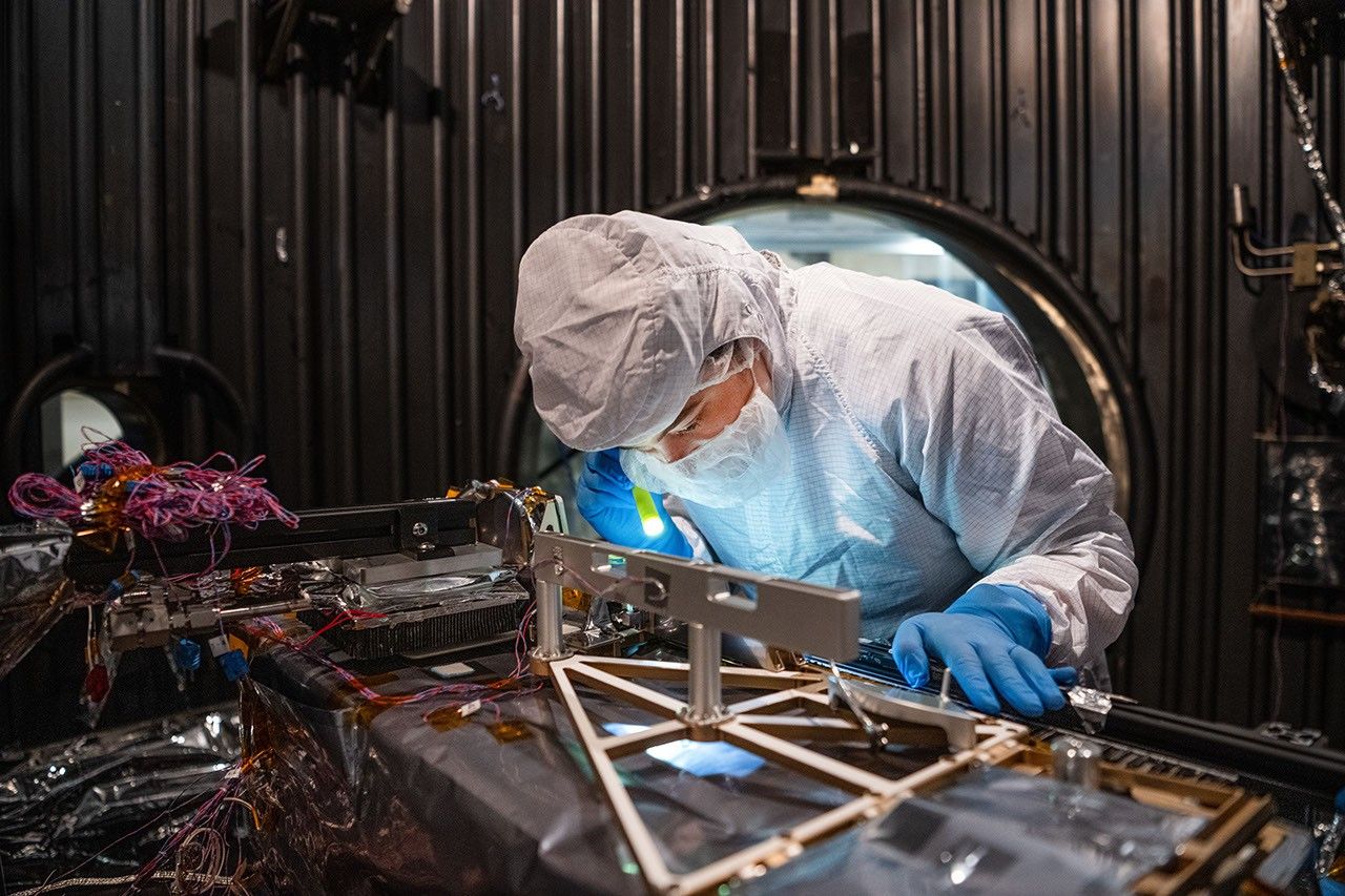
Mechanical Engineer Brie Ludwig inspects the Lunar Environment Monitoring Station (LEMS) in preparation for testing in a thermal vacuum chamber at Goddard Space Flight Center in Greenbelt, Maryland, on March 31, 2026. LEMS is a compact, autonomous, and self-sustaining seismometer suite designed to carry out continuous, long-term monitoring of the lunar seismic environment at the South Polar region.
NASA/Denny Henry

“When we conceived of LEMS, we weren’t just thinking about the next mission, we were thinking about the next generation of lunar exploration,” said Mehdi Benna, a University of Maryland Baltimore County scientist who leads LEMS from NASA Goddard. “Our vision was to create a scientific buoy for the Moon. Like an ocean buoy on Earth, LEMS is designed to be easy to build, adaptable to different scientific objectives, and capable of operating independently for years.”

Before any surface science could happen, Benna and his team had to ensure that LEMS could survive the trip to the Moon and the harsh environment of its surface. Over the past five months, LEMS and its components have been subjected to a demanding series of environmental and operational tests. Engineers verified LEMS can endure the violent shaking of launch, the journey to the lunar surface, and the Moon’s temperature and radiation environment. The team also showed that the instrument package’s mechanical and electrical design is safe for astronaut handling.

The LEMS payload was built to operate through the lunar night, which lasts two Earth weeks, without external power assistance or a heat source. Past lunar surface instruments relied on radioisotope heaters for warmth and power. But LEMS instead will withstand temperatures that dip to minus 400 degrees Fahrenheit in some areas by using advanced insulation materials, low-thermal-conductivity cables that minimize heat loss, and a thermal regulator that conducts heat away during the day to prevent overheating and helps retain heat at night.

These innovations reduce mass and power needs, setting the stage for lighter, energy-efficient instruments that can operate continuously at future Artemis landing sites and the NASA-led Moon Base.

The LEMS payload is led by University of Maryland Baltimore County and University of Maryland College Park. Technical implementation is led by NASA Goddard. The University of Arizona, in partnership with Silicon Audio, Inc., supplied LEMS’ two state-of-the-art seismometers. Morehead State University in Kentucky provided LEMS’ telecommunication system and will operate the instrument on the surface. Washington University in St. Louis will manage the instrument’s data processing and dissemination to the larger scientific community.

Source: science.nasa.gov
NASA Delivers Navigation System for Commercial Lunar Relay

4 Min Read

NASA Delivers Navigation System for Commercial Lunar Relay

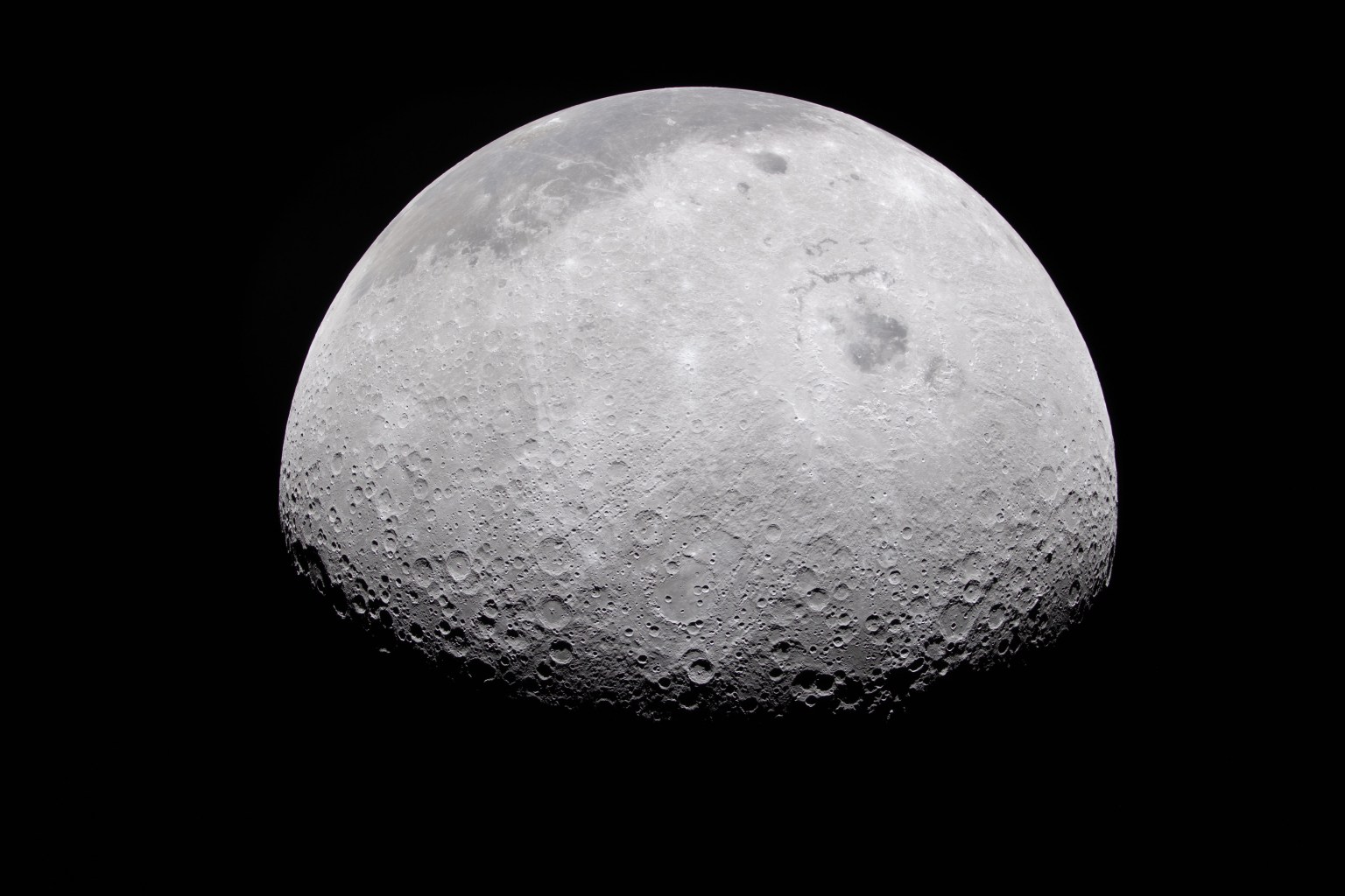
The Moon's rugged surface is on display in this image. Most of the Moon is visible, with the bottom of the sphere disappearing into the darkness. This line between light and dark is called the terminator. The terminator is lined with many craters.

The Moon’s rocky, uneven, and otherworldly surface features are highlighted by the terminator – the difference between light and darkness.

Credits:
NASA

NASA delivered the NavCube3-mini payload on July 13 to Intuitive Machines for integration into Altus-1, the company’s first lunar relay satellite, marking an important milestone in the development of future lunar communications and navigation services. The lunar relays are designed to enable communications and navigation for astronauts and rovers operating at the agency’s future Moon Base.

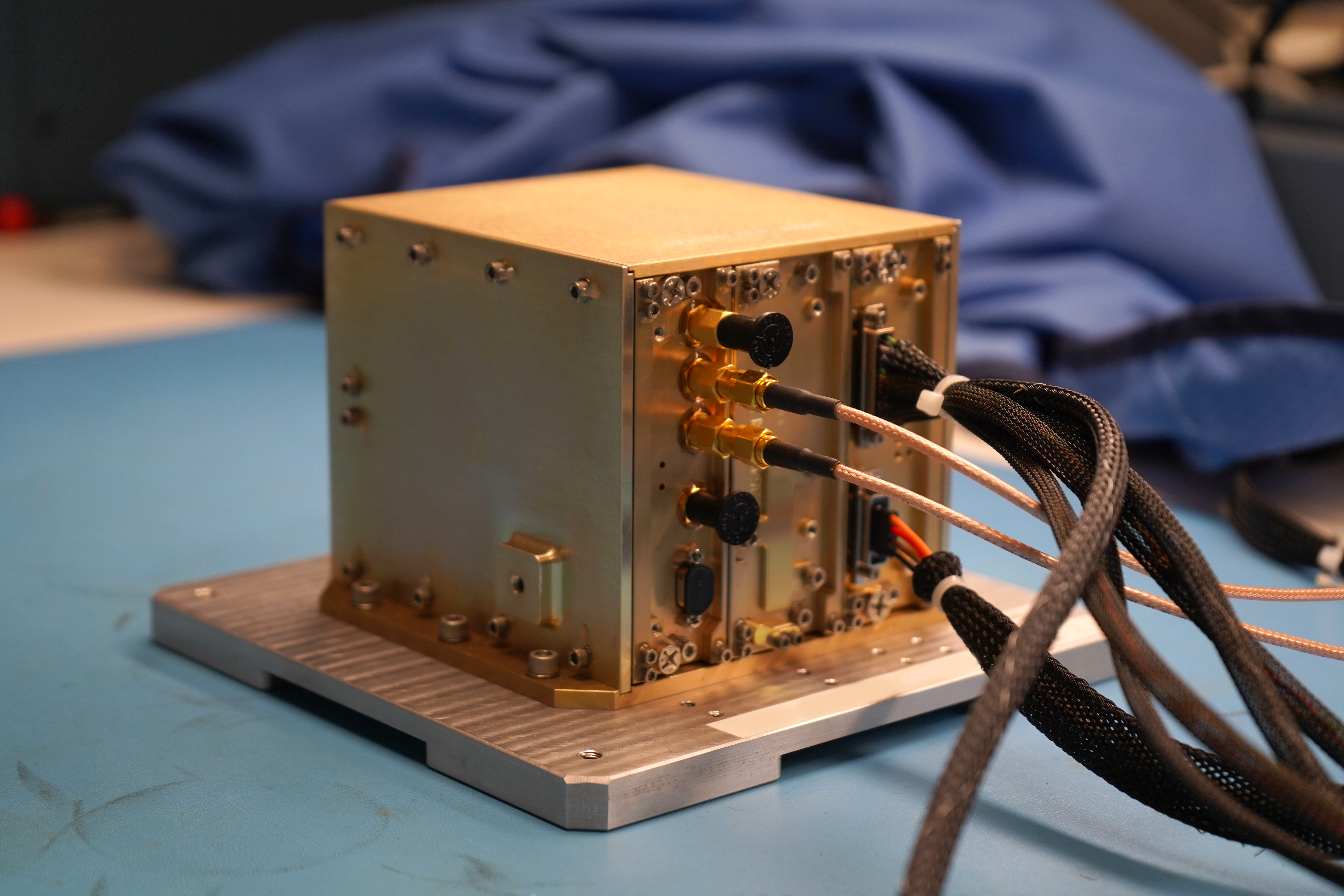
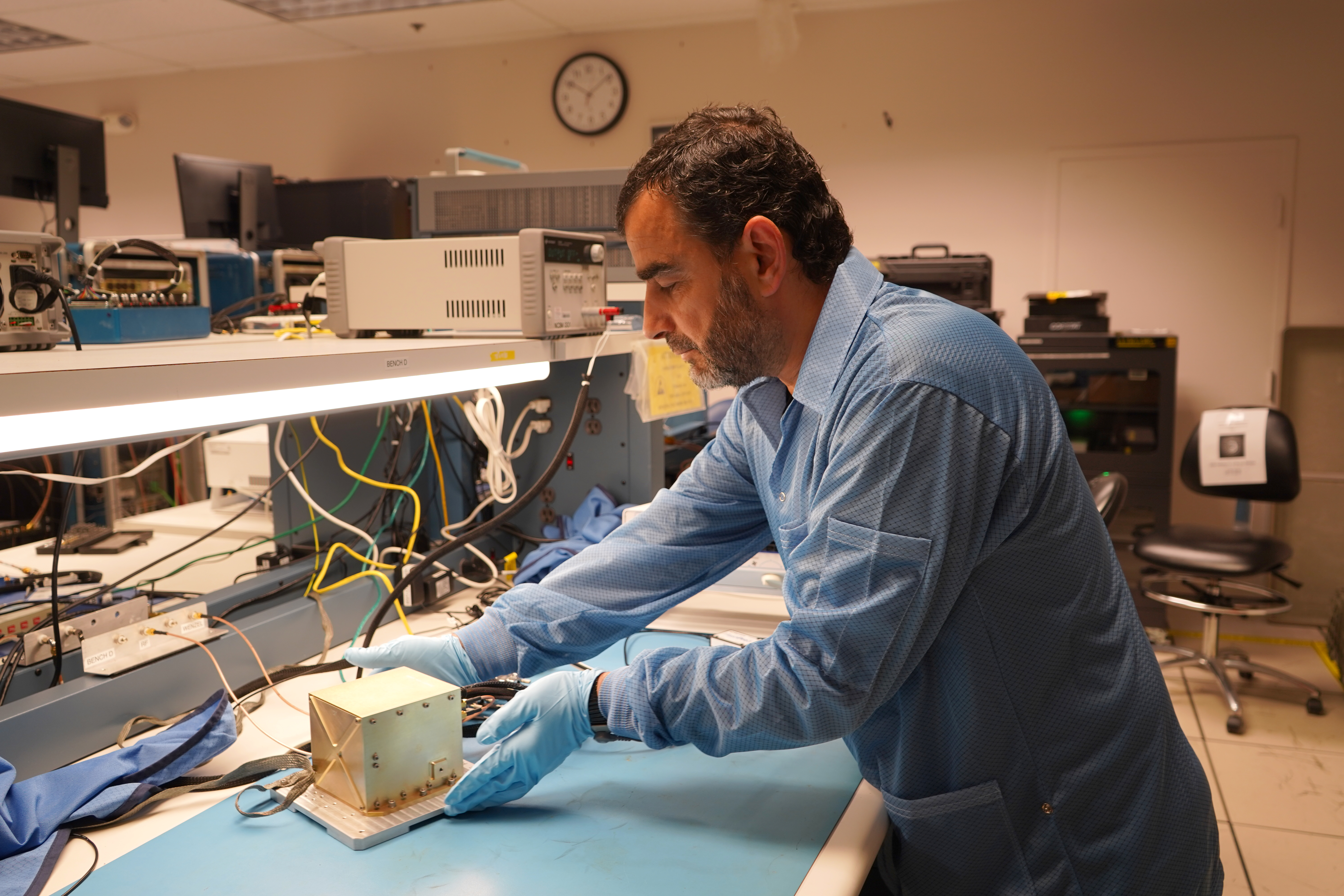
About half the size of a shoebox and weighing just 3.5 pounds, NavCube3-mini is a compact but powerful navigation receiver designed to use signals from Earth-based GPS and Galileo Global Navigation Satellite Systems (GNSS) at lunar distances. Operating on less than 20 watts of power, roughly the same as a laptop computer, it can determine a spacecraft’s precise position far beyond Earth orbit. The compact payload builds on a series of navigation technology advancements developed at NASA’s Goddard Space Flight Center in Greenbelt, Maryland, each extending GPS navigation to new record-breaking distances from Earth.

The NavCube3-mini payload in a laboratory at NASA's Goddard Space Flight Center in Greenbelt, Md.
NavCube3-mini in the Space Navigation Laboratory at NASA’s Goddard Space Flight Center in Greenbelt, Md., prior to delivery to Intuitive Machines for integration into the Altus-1 lunar relay satellite.
NASA/Dave Ryan

The payload will fly aboard Intuitive Machines’ Altus-1 lunar relay satellite, the first of a planned network of lunar relay satellites being developed under the company’s Near Space Network Services contract with NASA. The relays will provide communications and navigation support for missions operating at the Moon, including the challenging lunar South Pole region, where Artemis astronauts will land in 2028, and where direct communications with Earth can be difficult. By extending communications coverage and improving navigation services, the relay network will help realize NASA’s vision for a sustained human presence on the lunar surface.

Before being shipped to Intuitive Machines, NavCube3-mini underwent an extensive environmental and performance test campaign at NASA Goddard to verify it is ready for spaceflight. The environmental testing included vibration testing to simulate launch conditions, thermal vacuum testing in the extreme temperatures and vacuum of space, and electromagnetic compatibility testing to ensure the payload can operate reliably alongside other spacecraft systems without causing or experiencing electromagnetic interference. Performance testing was conducted before and after each environmental test using high-fidelity simulations of the GPS and Galileo signals the NavCube will encounter in lunar orbit, verifying functionality and performance throughout the testing campaign. 

The NavCube3-mini payload and project manager in a laboratory at NASA's Goddard Space Flight Center in Greenbelt, Md.
Munther Hassouneh, the NavCube3-mini project manager, in the Space Navigation Laboratory at NASA’s Goddard Space Flight Center in Greenbelt, Md.
NASA/Dave Ryan

NavCube3-mini will serve as a key technology demonstration aboard Altus-1, validating the use of GNSS-based navigation in the lunar region and providing valuable performance data to support the development of future lunar navigation infrastructure. This technology is part of NASA’s broader strategy to develop communications and navigation services that work across both commercial providers and NASA’s networks. These capabilities are designed to support a growing lunar ecosystem that includes orbiters, landers, rovers, and, eventually, astronauts living and working on the Moon.

The delivery of NavCube3-mini marks another step toward building the communications and navigation infrastructure needed for long-term lunar exploration. Through partnerships with commercial providers like Intuitive Machines, NASA is building a more connected and capable lunar environment. As activity around the Moon continues to grow, these capabilities will enable lunar spacecraft and explorers to operate more safely, efficiently, and autonomously.

About the Author

Katherine Schauer

Katherine Schauer

Katherine Schauer is a writer for the Space Communications and Navigation (SCaN) Program office and covers emerging technologies, commercialization efforts, exploration activities, and more.

Source: www.nasa.gov